4
Manual No. 016-0171-122 Rev. E 39
SENSOR INSTALLATION
INSTALL THE CENTER RACK SENSOR
90’ - 100’ BOOMS
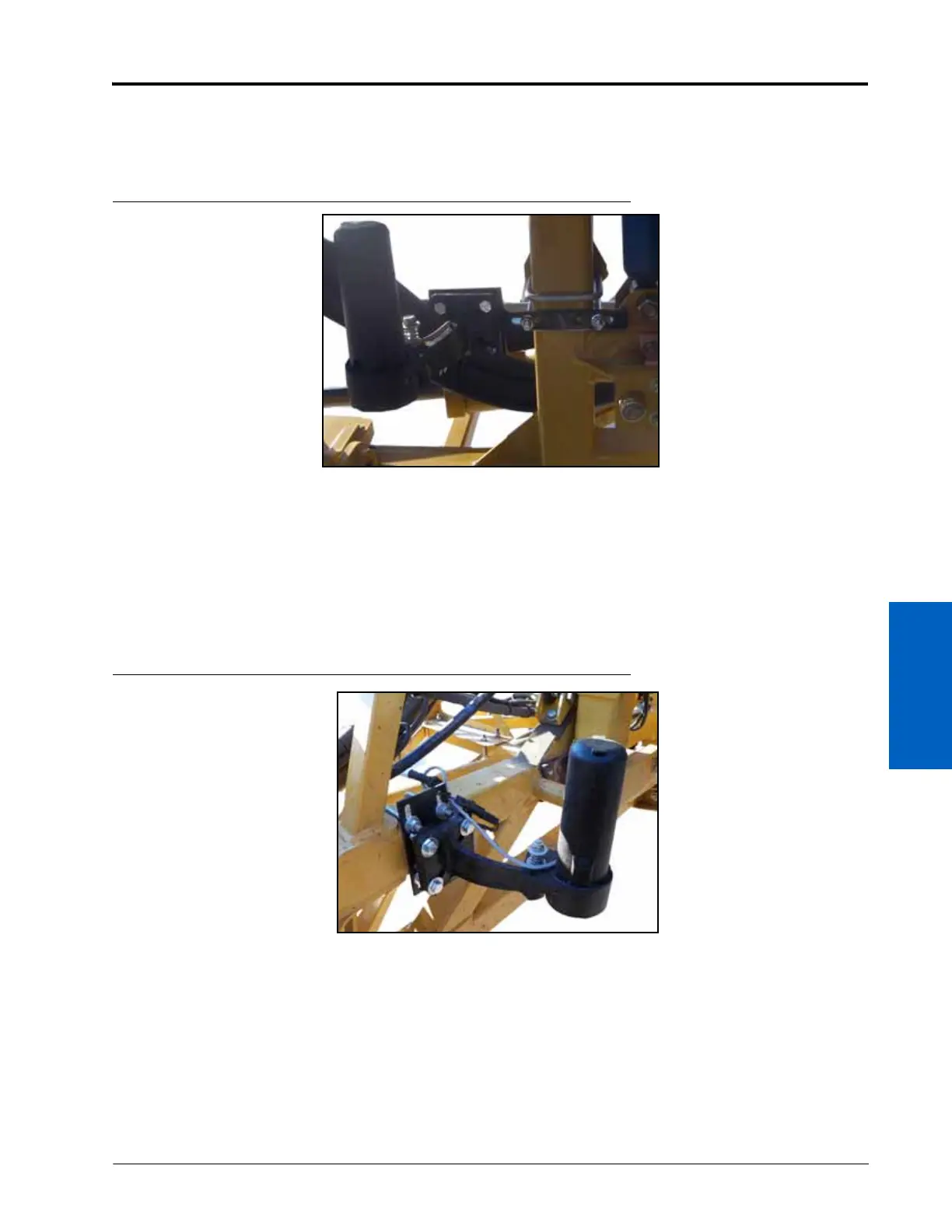
FIGURE 3. Center Rack Sensor Installed
1. Mount the center sensor mounting bracket (P/N 107-0171-349) to the machine’s center rack using a 3-1/16” x 4”
x 3/8” thread U-bolt (P/N 107-0171-608) and two 3/8” - 16” zinc flanged lock nuts (P/N 312-1001-164).
2. Secure the center sensor (P/N 063-0130-014) to the sensor mounting bracket using four 3/8” - 16 UNC x 1-1/4”
machine bolts (P/N 311-0054-106) and four 3/8” - 16 zinc flanged lock nuts (P/N 312-1001-164).
3. Tighten the nuts to ensure the sensor is mounted securely.
120’ BOOMS
FIGURE 4. Center Sensor Installed
1. Secure the center sensor (P/N 063-0130-014) to the ultrasonic sensor boom mount weldment bracket (P/N 116-
0159-684) using four 3/8”-16 UNC x 1-1/4” hex bolts (P/N 311-0054-106) and four 3/8”-16 zinc flanged lock nuts
(P/N 312-1001-164).
2. Mount the center sensor to the machine’s center rack using two 3-1/16” W x 4” L x 3/8” thread U-bolts (P/N
107-0171-608) and four 3/8” zinc flanged lock nuts (P/N 312-1001-164).
 Loading...

