CHAPTER 4
44 Viper Pro Installation & Operation Manual
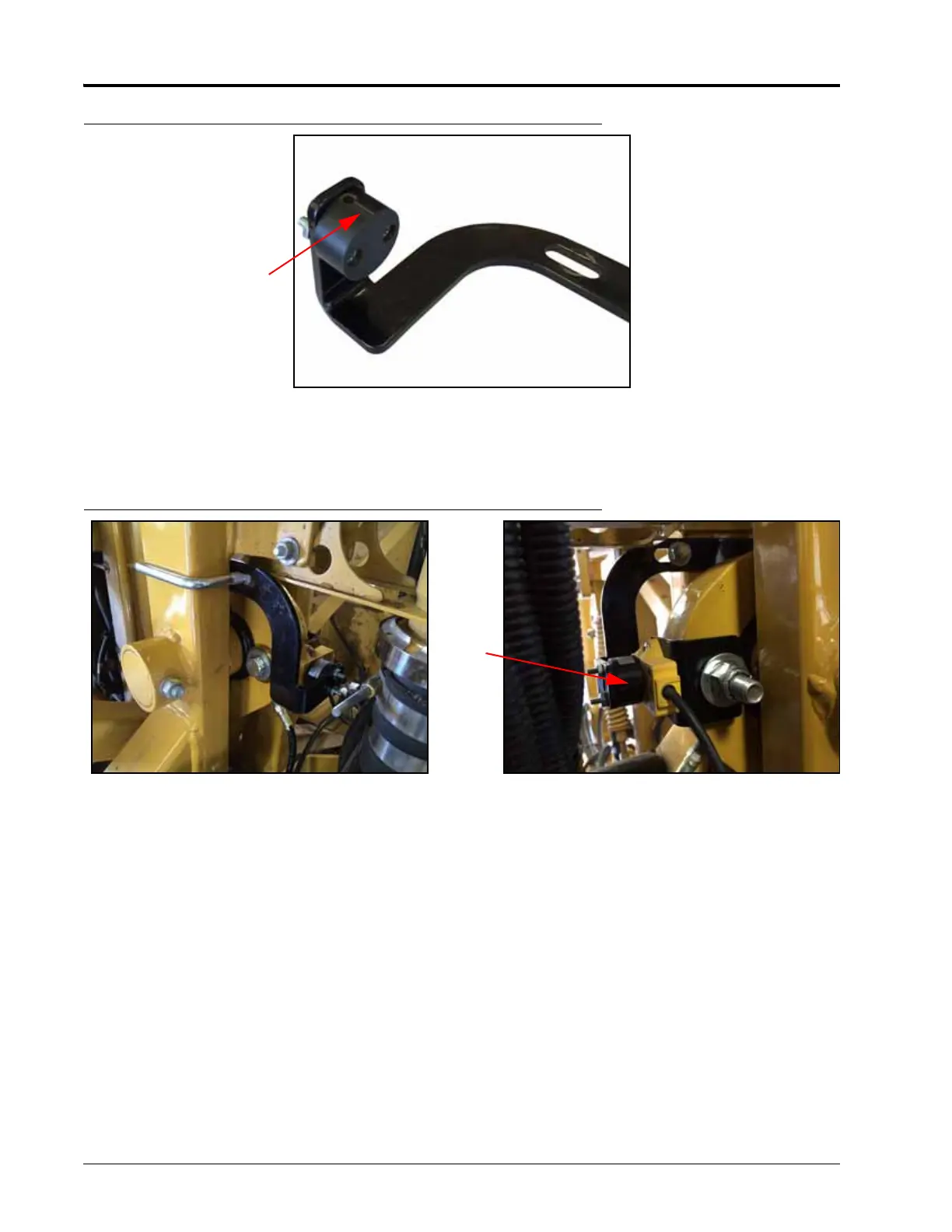
FIGURE 11. Puck Installed on Mounting Bracket
5. Install the black puck from the rotary sensor installation kit on the short leg of the UltraGlide XT bolt mounting
bracket (P/N 107-0172-178) using two #8-32 x 1-1/4” screws (P/N 311-0001-023) and two #8-32 hex nuts (P/N
312-1001-020).
FIGURE 12. UltraGlide XT Sensor Bolt Mounting Bracket Installed
6. Align the black puck with the rotary sensor, positioning the bracket as shown above.
7. Secure the bolt mounting bracket to the vertical support beam next to the pivot bearing using a 3-1/16” W x 2-
1/4” L x 3/8” thread U-bolt (P/N 107-0172-288) and two 3/8” flanged lock nuts (P/N 312-1001-164).
8. Adjust the mounting bracket so that the center of the puck aligns with the center of the rotary sensor and that
a clearance of less than 3 mm is maintained between the puck and the rotary sensor.
9. Tighten the mounting hardware to ensure the sensor is mounted securely.
 Loading...