19
Chapter 3: Installation
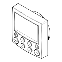
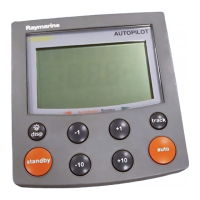
This chapter describes how to install the ST60+ Graphic Display.
For advice, or further information regarding the installation of this equipment,
please contact the Raymarine Product Support Department or your own National
Distributor.
3.1 Planning your installation
Before starting the installation, spend some time considering the best position for
the instrument, such that the
Site requirements
and the
EMC installation
guidelines
(below) are satisfied.
Site requirements
4.33 in (110 mm)
0.93 in
(23.5 mm)
0.6 in
(15 mm)
3.54 in (90 mm)
diameter
4.53 in (115 mm)
4.90 in (124 mm)
0.25 in
(6.50 mm)
1.4 in
(35 mm)
3.54 in (90 mm)
diameter
490 in (124 mm)
D8146-1
ST60+ instrument dimensions
With standard bezel
(surface mount)
With low profile bezel
(flush mount)
81268_3.book Page 19 Tuesday, August 1, 2006 8:05 AM

 Loading...


