26 ST60+ Graphic Display Owner’s Handbook
4. Cut out the aperture (3) for the assembled instrument and bezel and remove
the template.
5. Peel off the protective sheet from the self-adhesive gasket (4) then stick the
gasket into position on the rear of the bezel.
6. Screw the two fixing studs (1) into the threaded sockets on the rear of the
instrument.
7. Mount the assembled instrument, studs, bezel and gasket into the panel.
8. Locate the flush mount bracket (6) onto the fixing studs and secure the assem-
bly to the panel with the thumb-nuts (5).
Bracket mounting
A Control Unit Mounting Bracket (Part No. E25009) enables you to mount your
the ST60+ Graphic Display in locations where other forms of mounting are
impractical. Although this provides a useful alternative method for securing your
instrument, it is only suitable for use in positions where the instrument will not be
exposed to water.
To bracket mount your ST60+ instrument, do so in accordance with the Control
Unit Mounting Bracket Instruction Sheet.
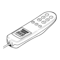
Auxiliary alarm option
The Auxiliary Alarm is waterproof and can be mounted on a panel either above or
below deck, as follows:
1. Drill a
7
/8 in (22 mm) diameter hole through the mounting panel as shown.
2. Insert the grommet supplied into the hole.
3. Feed the connecting wires through the drilled hole, then connect them to the
connector block.
4. Place the Auxiliary Alarm in position, and secure it using the four self-tapping
screws (supplied).
45mm (1.8in)85mm (3.35in)
D4411-2
Auxiliary Alarm
55 mm
(2.15 in)
81268_3.book Page 26 Tuesday, August 1, 2006 8:05 AM