1.5 Consideration of Surroundings
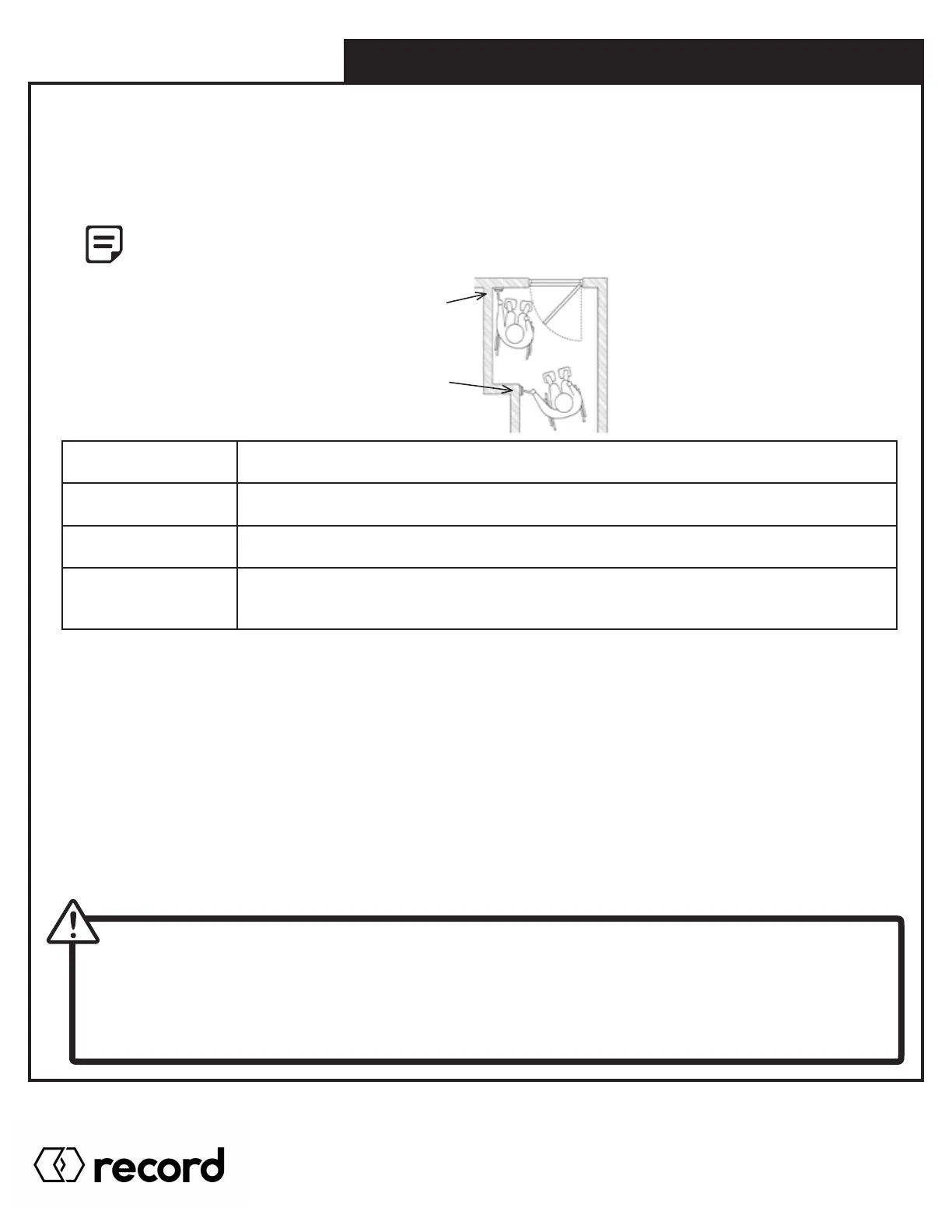
Floor Space Requirements for Wheel Chair Maneuvering - Americans with Disabilities Act (ADA)
The owner may request the activation device location; however, the press switch must be in view of the door and not
directly on the door or frame. Please refer to ANSI 117.1 Safety Code for further guidelines on switch requirements.
Activation switches shall be at minimum height of 36” and maximum height of 48” from finished floors.*
Individual who uses wheelchair needs a minimum of 48” clearance to the door swing for doors in
sequence application.
Position# 1
Minimum Two Feet (2’)
from door latch
External and Internal Factors
Position# 2
Minimum Five Feet (5’)
from door face
Door must move easily open and close (latch) without excessive force; weather stripping and
threshold must not interfere with door movement.
For out swing (Push) doors, the reveal must be within the range of 0” to 14”. For in swing (Pull)
doors, 0” to 4” for special reveals is allowed – for all others consult factory.
When installing on a door in a strong wind condition area, special adjustments should be made
to the arm and doorstop position, to increase the spring tension.
Check that the electrical feed, all conduits, and electrical junction boxes (for push plates or
other activation devices, if required) are correctly located in accordance with final approved
shop drawings and within the guidelines of the enforced local electrical codes.
1.6 Electrical
The 115±5VAC supply lines are connected to the black primary wires coming from the transformer and the ground wire is
attached to the operator header box. Mount the ON/OFF/HOLD OPEN switch in the header end plates to the latch side of the
unit (or closest to the control board).
The control board settings have been pre-set prior to shipment. It will be necessary for the door operator to be functional while
adjustments and settings are made. A black push actuator is mounted on the upper left corner of the circuit board to ease
in the adjustment process. Power up the unit, push an activating device and check to make sure that the spline pinion drive
rotates in the correct direction. Keep all wires away from moving parts and sharp edges that may cut into the outer casing of
the wires.
THE GROUND WIRE FOR THE INCOMING 115±5VAC POWER AND THE SYSTEM GROUND WIRE
CANNOT SHARE THE SAME GROUNDING STUD. GROUND THE INCOMING 115±5VAC ACCORDINGLY.
• Installation of any extra wiring for controls or accessories into the header unit shall be secured and away from
any moving parts.
• If the motor is not plugged into the circuit board, there is no resistance against the spring when manually opening
the door. The door or arm will close very quickly if opened.
* Check with local Authority
Having Jurisdiction
Pg. 12
HA8-SP Manual V. 7.0
Record Canada Inc.
Toll Free: 1-877-348-6837
info.ditec.ca@recorddoors.com
www.recorddoors.ca
Record USA Inc.
Toll Free: 1-866-901-4284
info.ditec.us@recorddoors.com
www.recorddoors.com