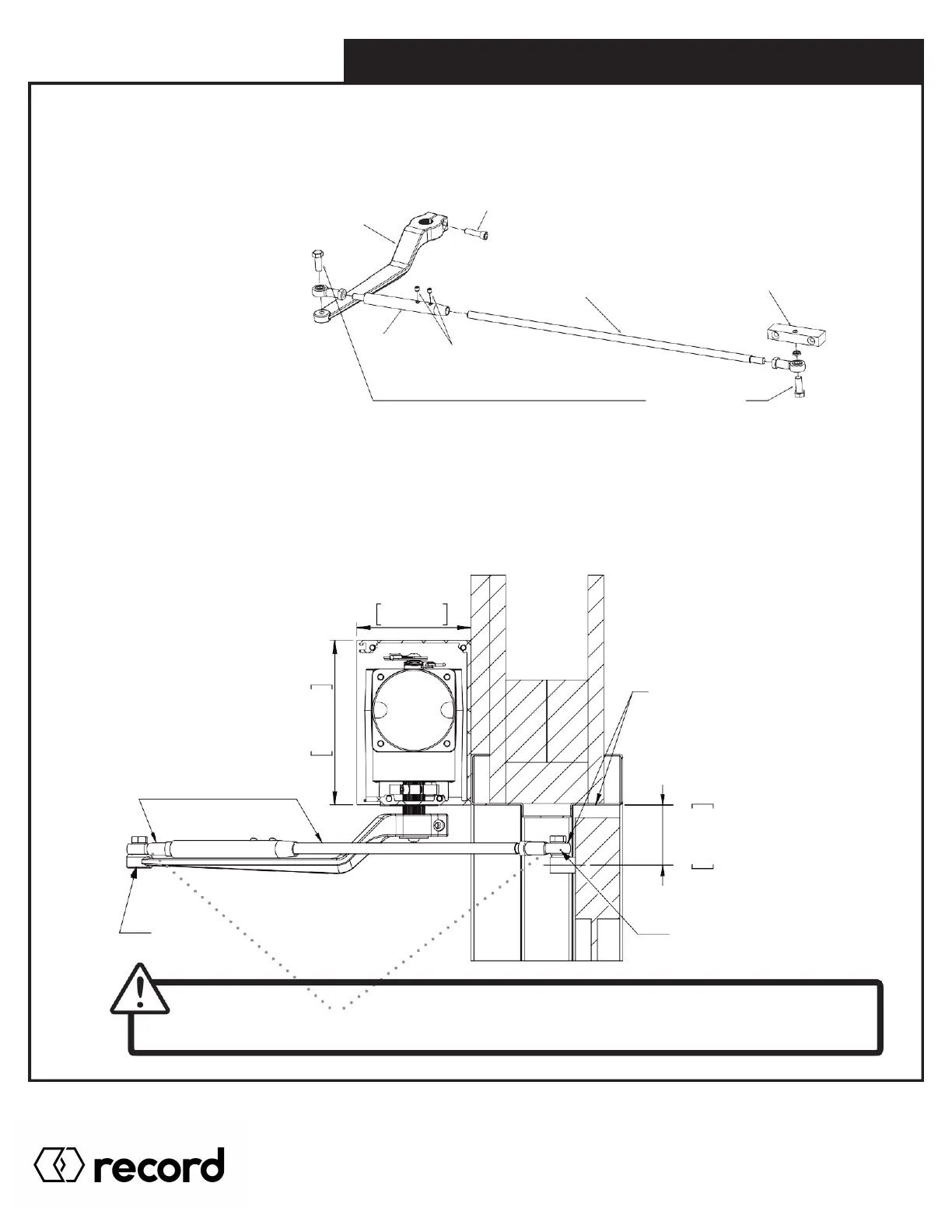
3.1 Push Arm Components & Configurations
The main arm components will consist of the Main handle, Sleeve, Adjustable rod (cut to length), and Door shoe,
as shown below.
MAIN HANDLE
M8x 25mm
SOCKET CAP SCREW
ADJUSTABLE ROD
(CUT TO LENGTH)
DOOR SHOE
SLEEVE
M6 x 6mm
FLAT POINT
SOCKET SET SCREW
M10 x 30mm
HEX CAP SCREW
There are two configurations available depends on available spacing.
Option 1 - Standard Configuration
This is the standard configuration for the Push arm, the Sleeve and Rod are above the Main handle. Use this configuration
when there is no issue with clearance between the Rod/Door shoe and top jamb of the door frame. The Rod and Sleeve
are flexible at the ends where they are bolted (semi-ball joint) which will provide additional flexibility during install.
4.5in
114mm
OPTION 1 USED WHEN
CLEARANCE BETWEEN
TOP JAMB AND PUSH
ROD IS NOT AN ISSUE
SLEEVE AND ROD
ABOVE MAIN HANDLE
FLEXIBLE PUSH
ROD JOINT
FLEXIBLE PUSH
ROD JOINT
WARNING!
Please ensure Shoe Bolts at these joints are tightened after installation of arm is complete.
2.4in
60mm
GUIDELINE
DIMENSION
Pg. 22
HA8-SP Manual V. 7.0
Record Canada Inc.
Toll Free: 1-877-348-6837
info.ditec.ca@recorddoors.com
www.recorddoors.ca
Record USA Inc.
Toll Free: 1-866-901-4284
info.ditec.us@recorddoors.com
www.recorddoors.com