R8C/1A Group, R8C/1B Group 14. Timers
Rev.1.30 Dec 08, 2006 Page 144 of 315
REJ09B0252-0130
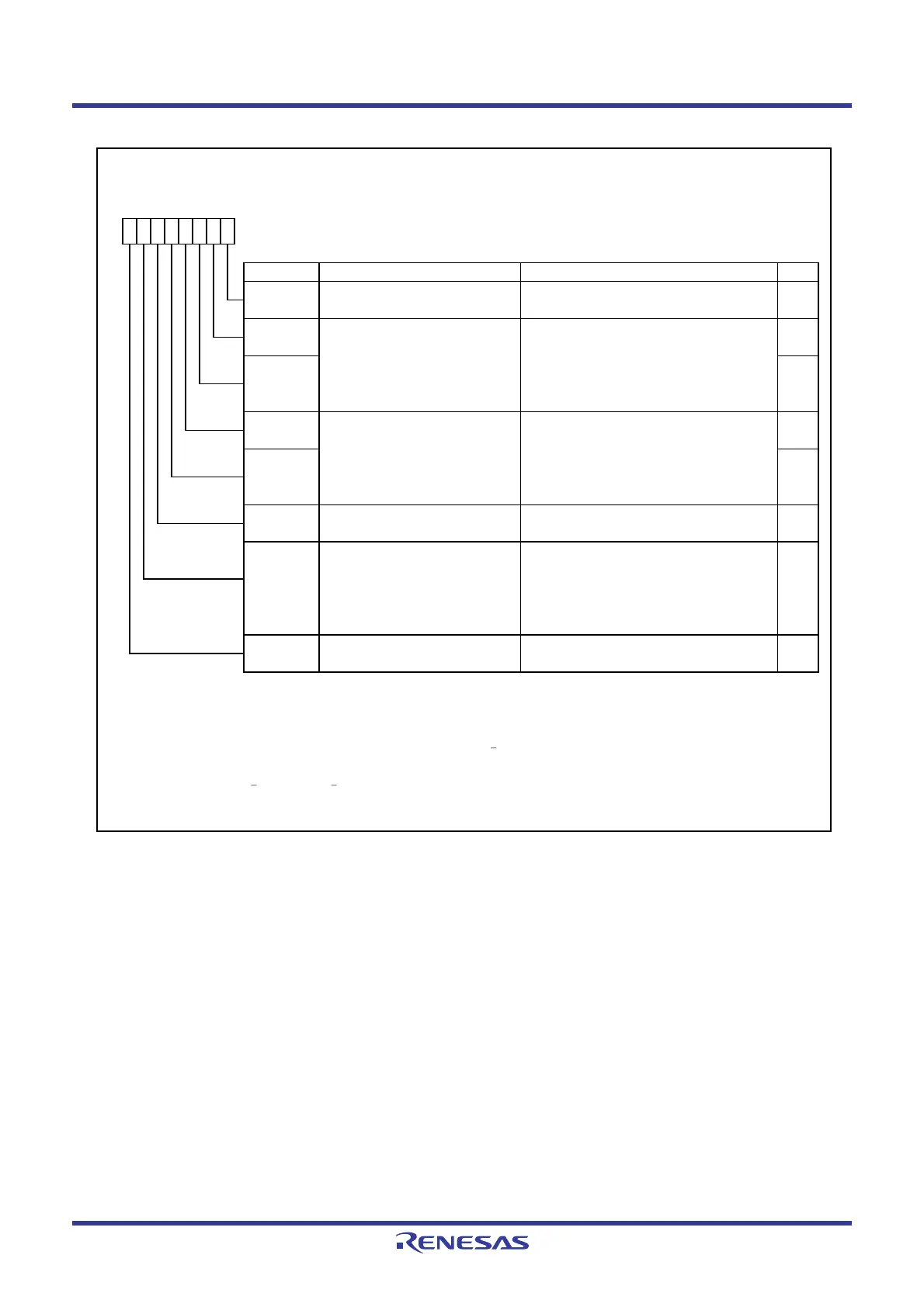
Figure 14.27 TCC0 Register
Timer C Control Register 0
Symbol Address After Reset
TCC0
009Ah 00h
Bit Symbol Bit Name Function RW
INT3
____
interrupt / capture polarity
select bits
(1, 2)
INT3
____
interrupt generation timing 0 : INT3
____
Interrupt is generated in
select bit
(2, 3)
synchronization w ith timer C count
source.
1 : INT3
____
Interrupt is generated w hen
INT3
____
interrupt is input.
(4)
INT3
____
interrupt / capture input 0 : INT3
____
switch bit
(1, 2)
1 : fRING128
NOTES :
1.
2.
3.
4.
b4 b3
0 0 : Rising edge
0 1 : Falling edge
1 0 : Both edges
1 1 : Do not set.
RWTCC06
RW
TCC04 RW
TCC03
Set to 0.
b7 b6 b5 b4
0
b3 b2 b1 b0
TCC01 RW
Timer C count start bit 0 : Stops counting.
1 : Starts counting.
Timer C count source select bits
(1)
b2 b1
0 0 : f1
0 1 : f8
1 0 : f32
1 1 : fRING-fast
TCC02 RW
TCC00 RW
When using the INT3
____
filter, the INT3
____
interrupt is generated in synchronization w ith the clock for the digital filter.
RW
Change this bit w hen the TCC00 bit is set to 0 (count stops).
The IR bit in the INT3IC register may be set to 1 (requests interrupt) w hen the TCC03, TCC04, TCC06, or TCC07 bit is
rew ritten. Refer to
12.5.5 Changing Interrupt Sources.
RW
Reserved bit—
(b5)
TCC07
When the TCC13 bit is set to 1 (output compare mode) and INT3
____
interrupt is input, regardless of the
setting value of the TCC06 bit, an interrupt request is generated.
 Loading...


