R8C/1A Group, R8C/1B Group 16. Clock Synchronous Serial Interface
Rev.1.30 Dec 08, 2006 Page 203 of 315
REJ09B0252-0130
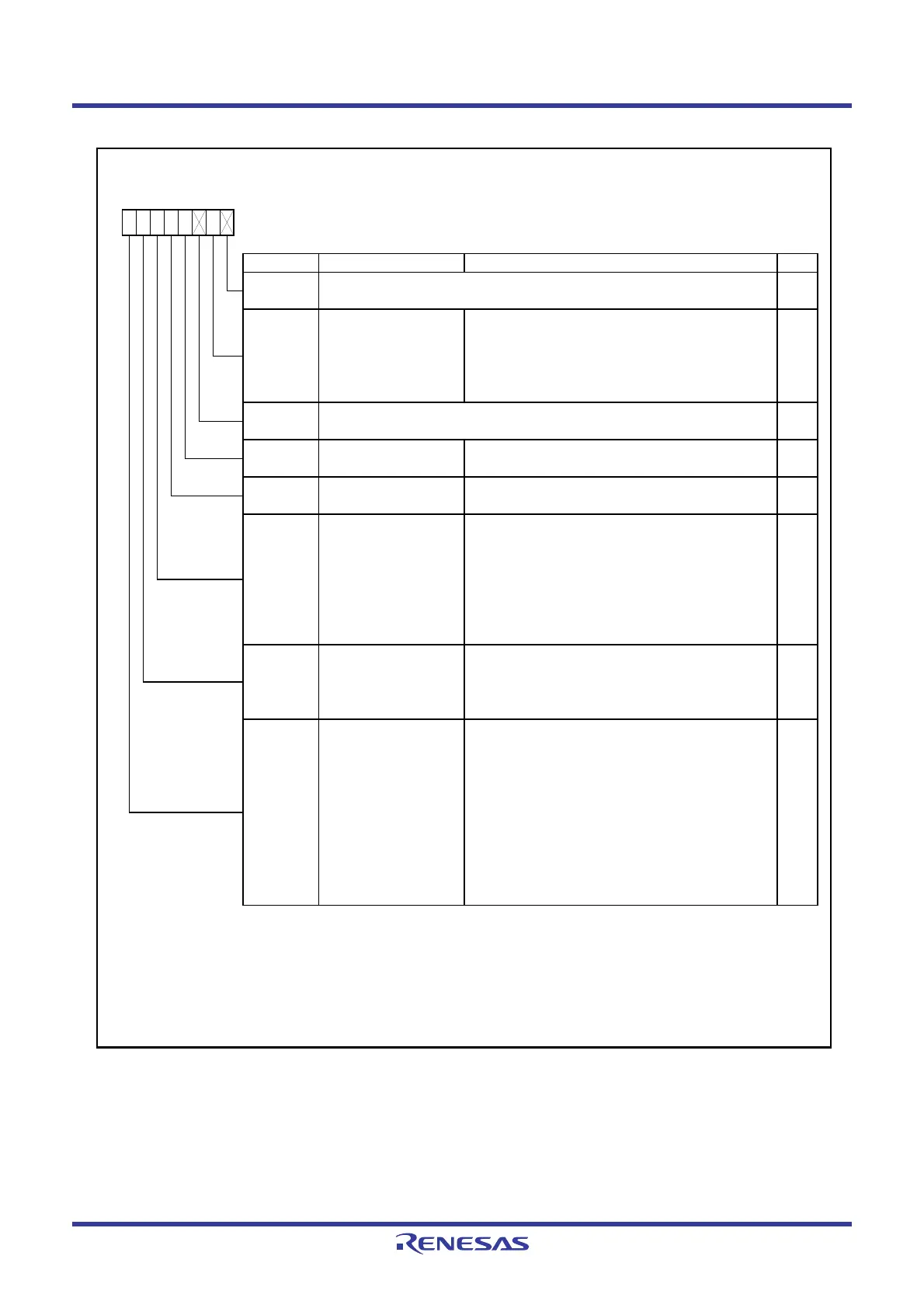
Figure 16.25 ICCR2 Register
IIC bus Control Register 2
(5)
Symbol Address After Reset
ICCR2
00B9h 01111101b
Bit Symbol Bit Name Function RW
NOTES :
1.
2.
3.
4.
5. Refer to
16.3.8.1 Accessing of Registers Associated with I
2
C bus Interface
for more information.
SCP
Start/stop condition
generation disable bit
When w riting to the BBSY bit, w rite 0
simultaneously
(3)
.
When read, the content is 1.
Writing 1 is invalid.
RW
When read
0 : Bus is in released state
(SDA signal changes from “L” to “H” w hile SCL
signal is in “H” state).
1 : Bus is in occupied state
(SDA signal changes from “H” to “L” w hile SCL
signal is in “H” state).
When w ritten
(3)
0 : Generates stop condition.
1 : Generates start condition.
RW
This bit is disabled w hen the clock synchronous serial format is used.
This bit is enabled in master mode. When w riting to the BBSY bit, w rite 0 to the SCP bit using the MOV
instruction simultaneously. Execute the same w ay w hen the start condition is regenerating.
When w riting to the SDAO bit, w rite 0 to the SDAOP bit using the MOV instruction simultaneously.
Do not w rite during a transfer operation.
SDAOP
SDAO RW
When read
0 : SDA pin output is held “L”.
1 : SDA pin output is held “H”.
When w ritten
(1,2)
0 : SDA pin output is changed to “L”.
1 : SDA pin output is changed to high-impedance
(“H” output via external pull-up resistor).
SDA output value control
bit
SDAO w rite protect bit When rew rite to SDAO bit, w rite 0 simultaneously
(1)
.
When read, the content is
1.
BBSY
Bus busy bit
(4)
—
(b2)
Nothing is assigned. If necessary, set to 0.
When read, the content is 1.
SCLO
SCL monitor flag 0 : SCL pin is set to “L”.
1 : SCL pin is set to “H”.
b7 b6 b5 b4 b0b3 b2 b1
—
(b0)
Nothing is assigned. If necessary, set to 0.
When read, the content is 1.
—
IICRST RW
When hang-up occurs due to communication failure
during I
2
C bus interface operation, w rite 1, to reset the
control block of the I
2
C bus interface w ithout setting
ports or initializing registers.
RO
RW
—
IIC control part reset bit
 Loading...


