R8C/1A Group, R8C/1B Group 16. Clock Synchronous Serial Interface
Rev.1.30 Dec 08, 2006 Page 204 of 315
REJ09B0252-0130
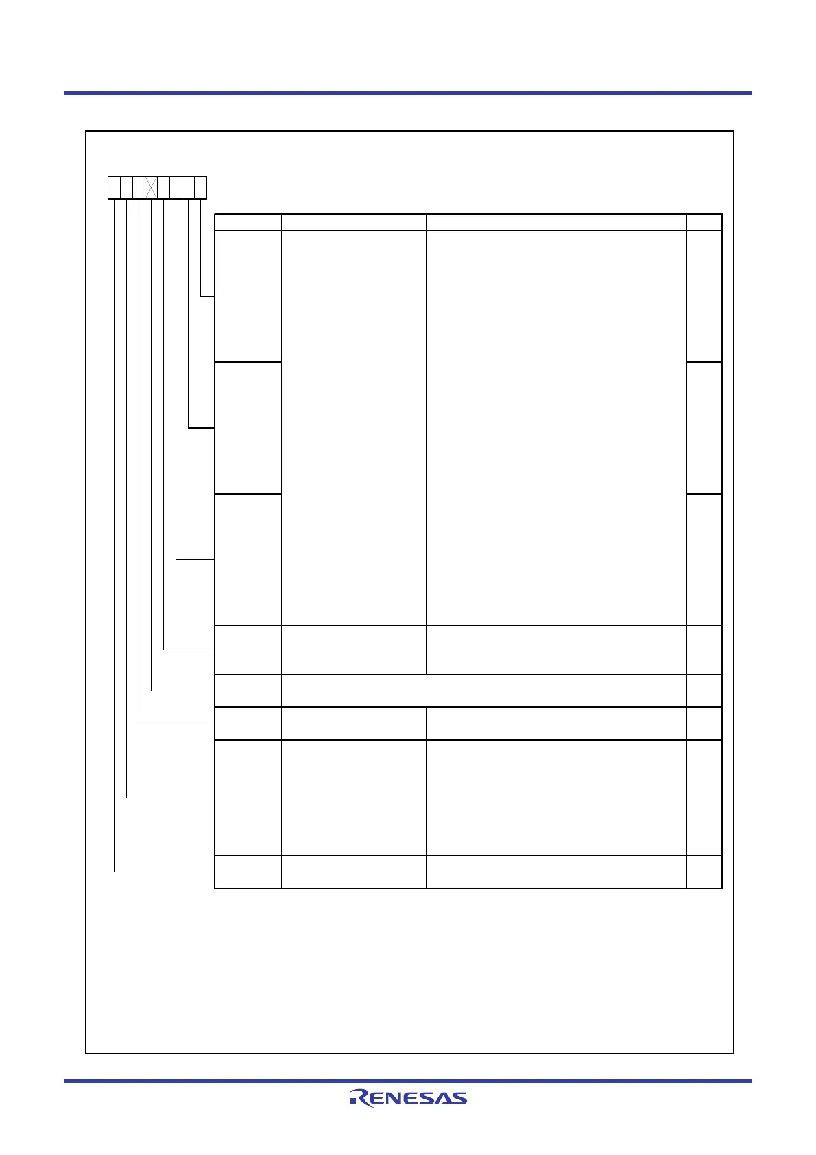
Figure 16.26 ICMR Register
IIC bus Mode Register
(7)
Symbol Address After Reset
ICMR 00BAh 00011000b
Bit Symbol Bit Name Function RW
MSB-first / LSB-first select
bit
NOTES :
1.
2.
3.
4.
5.
6.
7. Refer to
16.3.8.1 Accessing of Registers Associated with I
2
C bus Interface
for more information.
MLS RW
RW
BC1
BC2
Bit counter 2 to 0 I
2
C bus format (remaining transfer bit count w hen
read out and data bit count of next transfer w hen
w ritten.)
(1,2)
b2 b1 b0
0 0 0 : 9 bits
(3)
0 0 1 : 2 bits
0 1 0 : 3 bits
0 1 1 : 4 bits
1 0 0 : 5 bits
1 0 1 : 6 bits
1 1 0 : 7 bits
1 1 1 : 8 bits
Clock synchronous serial format (w hen read, the
remaining transfer bit count and w hen w ritten,
000b.)
b2 b1 b0
0 0 0 : 8 bits
0 0 1 : 1 bit
0 1 0 : 2 bits
0 1 1 : 3 bits
1 0 0 : 4 bits
1 0 1 : 5 bits
1 1 0 : 6 bits
1 1 1 : 7 bits
BC0
RW
RW
0
BCWP
BC w rite protect bit
b7 b6 b5 b4 b3 b2 b1 b0
When rew riting bits BC0 to BC2, w rite 0
simultaneously
(2,4)
.
When read, the content is 1.
RW
The setting value is enabled in master mode of the I
2
C bus format. It is disabled in slave mode of the I
2
C
bus format or w hen the clock synchronous serial format is used.
0 : No w ait
(Transfer data and acknow ledge bit
consecutively)
1 : Wait
(After the clock falls for the final
data bit, “L” period is extended for tw o
transfer clocks cycles.)
Set to 0.
RW
RW
0 : Data transfer MSB-first
(6)
1 : Data transfer LSB-first
—
(b5)
WAIT
Set to 0 w hen the I
2
C bus format is used.
When w ritin
to bits BC0 to BC2, w rite 0 to the BCWP bit usin
the MOV instruction.
—
(b4)
Nothing is assigned. If necessary, set to 0.
When read, the content is 1.
—
Rew rite betw een transfer frames. When w ritin
values other than 000b, w rite w hen the SCL si
nal is “L”.
After data including the acknow ledge bit is transferred, these bits are automatically set to 000b. When the start
condition is detected, these bits are automatically set to 000b.
Do not rew rite w hen the clock s
nchronous serial format is used.
Reserved bit
Wait insertion bit
(5)
 Loading...


