R8C/1A Group, R8C/1B Group 19. Electrical Characteristics
Rev.1.30 Dec 08, 2006 Page 280 of 315
REJ09B0252-0130
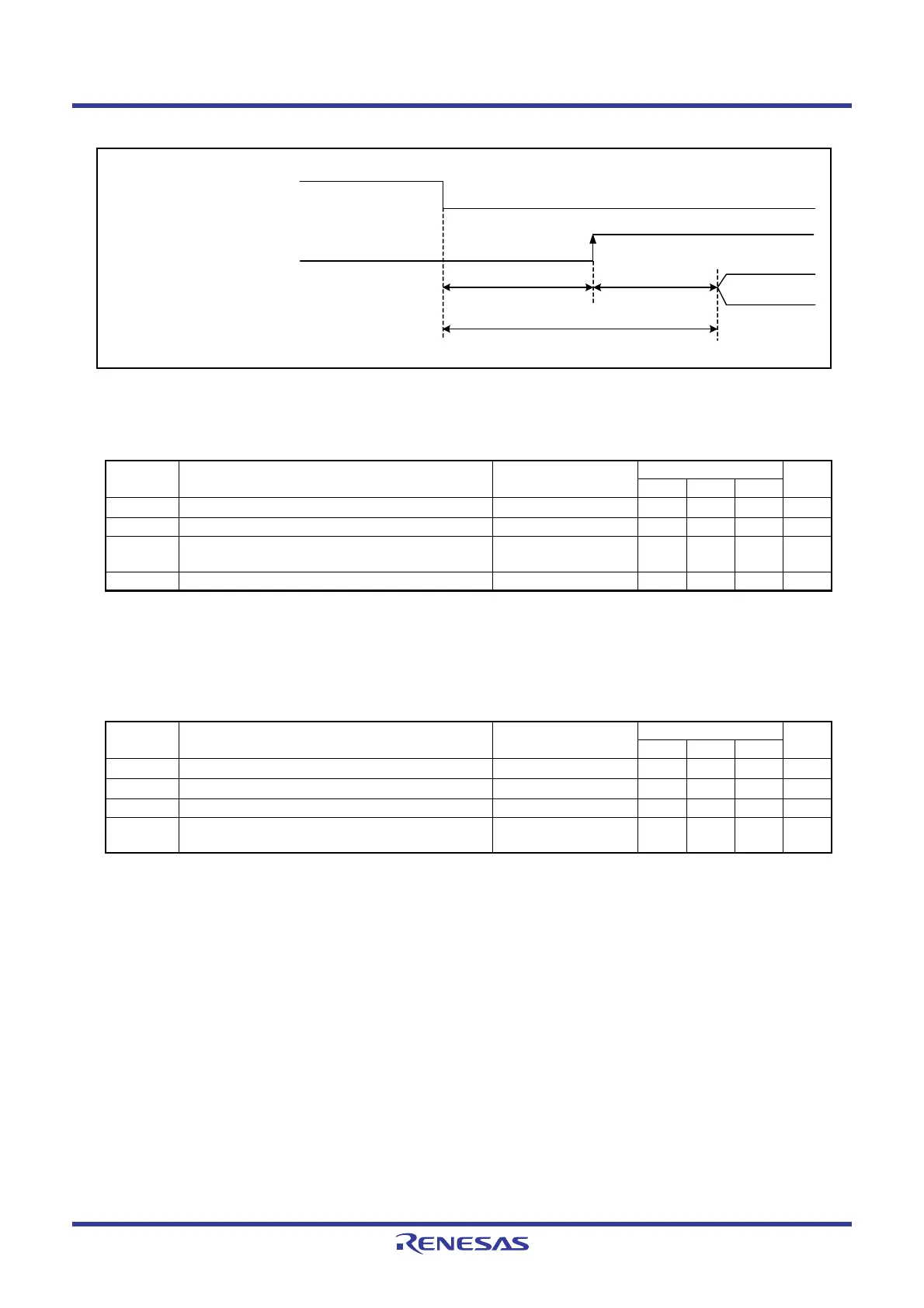
Figure 19.2 Transition Time to Suspend
NOTES:
1. The measurement condition is V
CC = 2.7 V to 5.5 V and Topr = -40°C to 85 °C.
2. Necessary time until the voltage detection circuit operates when setting to 1 again after setting the VCA26 bit in the VCA2
register to 0.
3. Ensure that V
det2 > Vdet1.
NOTES:
1. The measurement condition is V
CC = 2.7 V to 5.5 V and Topr = -40°C to 85 °C.
2. Time until the voltage monitor 2 interrupt request is generated after the voltage passes V
det2.
3. Necessary time until the voltage detection circuit operates when setting to 1 again after setting the VCA27 bit in the VCA2
register to 0.
4. Ensure that V
det2 > Vdet1.
Table 19.6 Voltage Detection 1 Circuit Electrical Characteristics
Symbol Parameter Condition
Standard
Unit
Min. Typ. Max.
V
det1
Voltage detection level
(3)
2.70 2.85 3.00 V
− Voltage detection circuit self power consumption VCA26 = 1, VCC = 5.0 V − 600 − nA
t
d(E-A) Waiting time until voltage detection circuit operation
starts
(2)
−−100 µs
Vccmin MCU operating voltage minimum value 2.7
−−V
Table 19.7 Voltage Detection 2 Circuit Electrical Characteristics
Symbol Parameter Condition
Standard
Unit
Min. Typ. Max.
V
det2
Voltage detection level
(4)
3.00 3.30 3.60 V
−
Voltage monitor 2 interrupt request generation time
(2)
− 40 −µs
− Voltage detection circuit self power consumption VCA27 = 1, VCC = 5.0 V − 600 − nA
t
d(E-A) Waiting time until voltage detection circuit operation
starts
(3)
−−100 µs
FMR46
Suspend request
(maskable interrupt request)
Fixed time (97 µs)
td(SR-SUS)
Clock-
dependent time
Access restart
 Loading...


