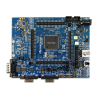
RH850/F1K Series Hardware Design Guide
R01AN2911EJ0100 Rev. 1.00 Page 2 of 46
Aug 04, 2016
Table of Contents
1. Power Supply.................................................................................................................. 6
1.1 Power Supply Overview of RH850/F1K Group ......................................................................... 6
1.1.1 Power Supply Pin Overview of RH850/F1K Group ................................................................. 6
1.1.2 Power Supply Pin Configuration of RH850/F1K Group .......................................................... 6
1.1.3 Power Supply Pin Architecture of RH850/F1K Group ............................................................ 6
1.1.4 Power Supply Timing of RH850/F1K Group ......................................................................... 10
1.2 Principle Capacitor Placement at REGVCC of RH850/F1K Group ....................................... 11
2. Minimum External Components .................................................................................. 12
2.1 Minimum External Components of RH850/F1K Group .......................................................... 12
3. Oscillator ....................................................................................................................... 15
3.1 Recommended Oscillator Circuit ............................................................................................ 15
3.1.1 Main Oscillator ...................................................................................................................... 15
3.1.2 Sub Oscillator ........................................................................................................................ 16
3.2 Recommended Oscillator Layout ............................................................................................ 16
4. Device Pins ................................................................................................................... 17
4.1 RESET ........................................................................................................................................ 17
4.1.1 Minimum RESET Circuit ....................................................................................................... 17
4.1.2 RESET Input Characteristics ................................................................................................ 18
4.2 General Purpose I/O .................................................................................................................. 19
4.2.1 RESET State of General Purpose I/O .................................................................................. 19
4.2.2 JP0_4/_DCUTRST ................................................................................................................ 19
4.2.3 P8_6/_RESETOUT/NMI/CSIH0CSS4/PWGA38O/RTCAOUT/ADCA0I8S .......................... 19
4.2.4 Analog Filter Function ........................................................................................................... 21
4.2.5 Behavior during Low Power Mode ........................................................................................ 22
4.3 Recommended Connection of unused Pins ........................................................................... 23
4.3.1 Recommended Connection of unused Pins for RH850/F1K Group ..................................... 23
4.4 Pin Assignment Differences .................................................................................................... 25
4.5 Injected Current ......................................................................................................................... 26
5. A/D-Converter ............................................................................................................... 27
5.1 Conversion Time ....................................................................................................................... 27
5.2 External Multiplexer Wait Time ................................................................................................ 27
5.3 Equivalent Input Circuit ............................................................................................................ 28
5.4 External Circuit on ADC Input .................................................................................................. 29
6. Development and Test Tool Interface ......................................................................... 31
6.1 Development Tool Interface of RH850/F1K Group................................................................. 32
6.1.1 Debug Interface Connection of RH850/F1K Group .............................................................. 32
6.1.2 Flash Programming Interface Connection of RH850/F1K Group ......................................... 36

 Loading...