EasyManuals Logo

Renesas RH850/F1K Series User Manual

Renesas RH850/F1K Series
49 pages
To Next Page IconTo Next Page
To Previous Page IconTo Previous Page
Page #35 background imageLoading...
Page #35 background image
RH850/F1K Series Hardware Design Guide
R01AN2911EJ0100 Rev. 1.00 Page 35 of 46
Aug 04, 2016
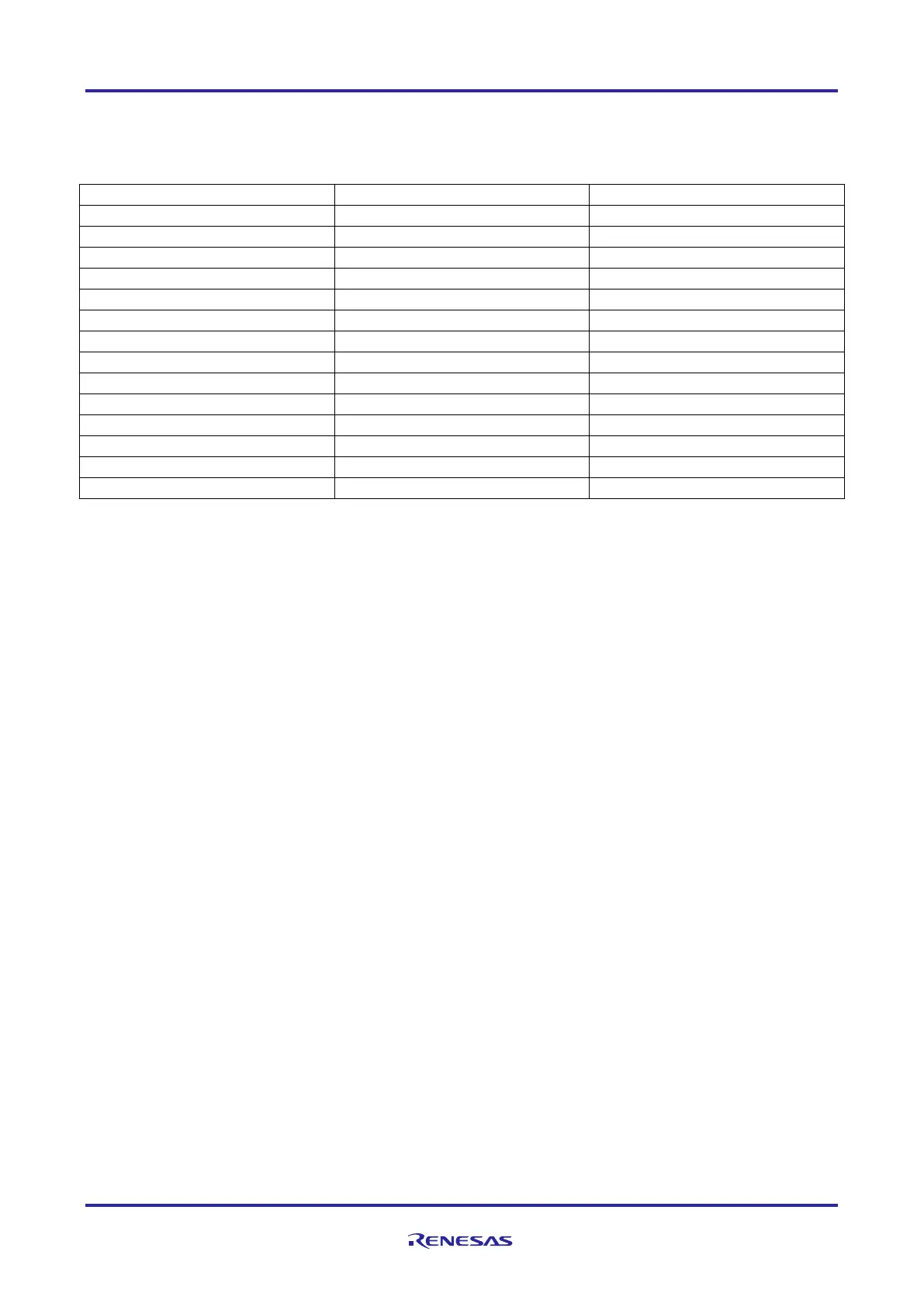
The debug interface signal connection of the E1 interface is given in the table below:
Table 21 Debug interface signal connection of RH850/F1K
E1 Interface Connector
E1 Interface Signal
RH850/F1K Device Pin
1
LPDCLK/(DCUTCK)
JP0_2
2
GND
EVSS
3
(DCUTRST)
JP0_4
4
FPMD0/FLMD0
FLMD0
5
LPDO/(DCUTDO)
JP0_1
6
FPMD1
FLMD1
7
LPDI/LPDIO/(DCUTDI)
JP0_0
8
TVDD
EVCC
9
(DCUTMS)
JP0_3
10
(EVTO)
JP0_6
11
LPDCLKOUT/(DCURDY)
JP0_5
12
GND
EVSS
13
RESET
RESET
14
GND
EVSS
Note: The Nexus interface signals marked with (text) are supported by 3rd party development tools and not by E1
emulator.
Caution:
When alternate port functions of P10_8/FLMD1 are used, please make sure not to drive a high level at reset.
When alternate port functions with pull-up resistor are used, please connect P10_8/FLMD1 to FPMD1 of
emulator. In that case, it is kept at a low level by the emulator when the reset signal is released.

Table of Contents

Questions and Answers:

Question and Answer IconNeed help?

Do you have a question about the Renesas RH850/F1K Series and is the answer not in the manual?

Renesas RH850/F1K Series Specifications

General IconGeneral
BrandRenesas
ModelRH850/F1K Series
CategoryPower Supply
LanguageEnglish