RH850/F1K Series Hardware Design Guide
R01AN2911EJ0100 Rev. 1.00 Page 11 of 46
Aug 04, 2016
1.2 Principle Capacitor Placement at REGVCC of RH850/F1K Group
When the data flash of the RH850/F1K group will be used in the application it should be considered to add an
additional capacitor to the REGVCC pin and to use a close component placement to the supply pin in order to optimize
the EMI noise behavior during the program and erase operation of the data flash.
The following recommendations shall be considered for the capacitor placement of the additional capacitor for EMI
optimization during data flash operation at the REGVCC pin:
Capacitor: 4.7µF to 10µF
Pin: REGVCC
Layout/distance: Capacitor within 10mm from mounting pad
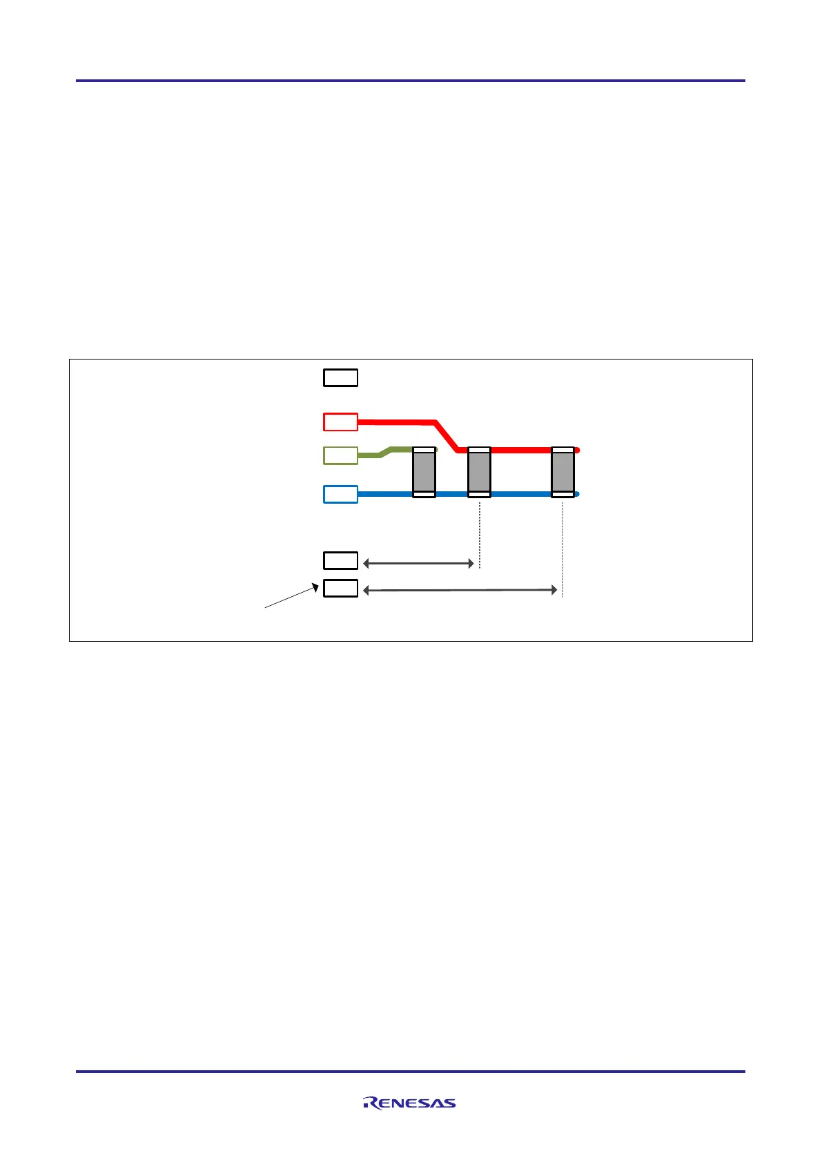
Figure 3 Principle capacitor placement at REGVCC for EMI at data flash operation
Mounting pad
AWOVSS
AWOVCL
REGVCC
0.1µF
for
AWOVCL
4.7µF to 10µF
for REGVCC to
optimize noise
during Data
Flash P/W
max. 4mm
max. 10mm
0.1µF
for
REGVCC
...
...
 Loading...