RH850/F1K Series Hardware Design Guide
R01AN2911EJ0100 Rev. 1.00 Page 12 of 46
Aug 04, 2016
2. Minimum External Components
The RH850/F1K series requires a certain number of external connections and components for a proper operation in
normal operation mode. The components are shown in different categories depending on the device operation and the
use case.
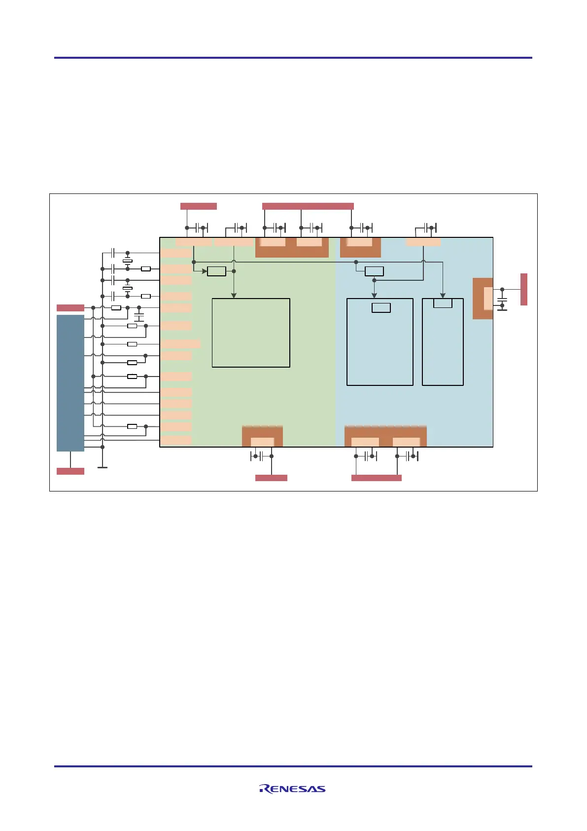
2.1 Minimum External Components of RH850/F1K Group
Figure 4 Minimum external components for RH850/F1K (176pin) for normal operation mode
Note: The debug interface connections shown covers Nexus, LPD 1pin and LPD 4pin. For details of the single debug
connection, please refer to the corresponding debug interface connection chapter. For details of other external
components, refer to their related chapters.
Port
EVCC EVCC
ADCA1
AD1
Port
EVCC ISOVCL
Port
EVCCREGVCC AWOVCL
ADCA0
AD0
A0VREF
C5
EVCC
C6 C7
C8
A1VREF
C10C11
REGVCC
C9C14 C13
X1
X2
IP0_0
XT 1
RESET
FLMD0
P10_8/FLMD1
DCUTRST
DCUTDI
DCUTDO
DCUCLK
DCURDY
DCUTMS
EVCC
C12
EVCC
Debug
VDD
REG
Logic
Logic Flash
REG
REG
C1
Q1
Q2
C2
C3
C4
R1
R2
R3
R4
R5
Core
C15
R6
EVTO
EVCC
R7
R8
 Loading...