RH850/F1K Series Hardware Design Guide
R01AN2911EJ0100 Rev. 1.00 Page 15 of 46
Aug 04, 2016
3. Oscillator
3.1 Recommended Oscillator Circuit
3.1.1 Main Oscillator
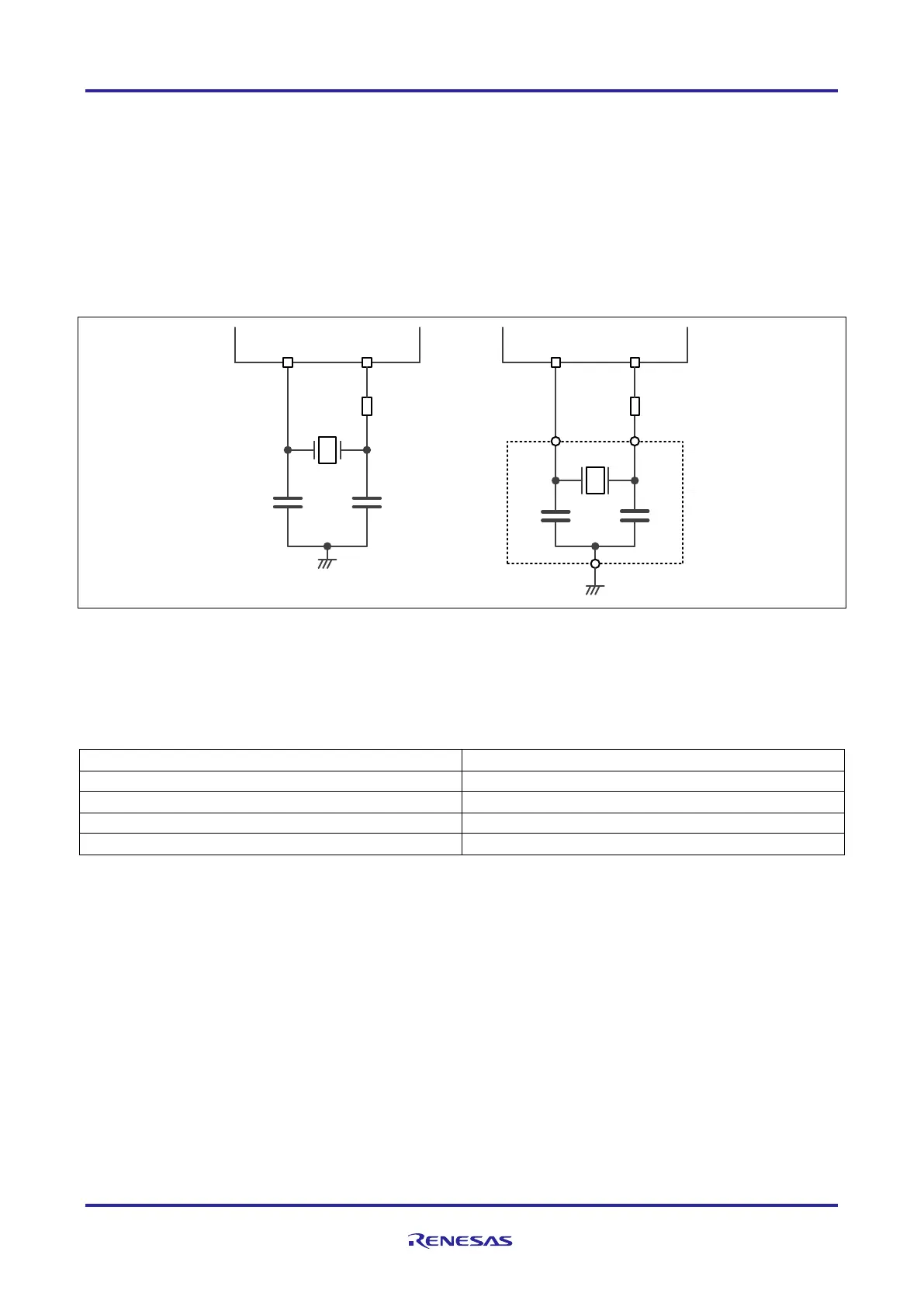
A crystal or ceramic resonator can be connected to the main clock input pins as shown below.
Figure 5 Recommended main oscillator circuit
General guidance values of the main oscillator circuit:
Table 9 Guidance values of the main oscillator circuit
Caution
Values of C1, C2 and Rd depend on the use of ceramic or crystal resonator and must be specified in cooperation
with ceramic or crystal resonator manufacturer.
X1 X2
MOSC
C2C1
Rd
internal
external
X1 X2
MOSC
C2
C1
Rd
internal
external
 Loading...