63
Preparationofthedisplay
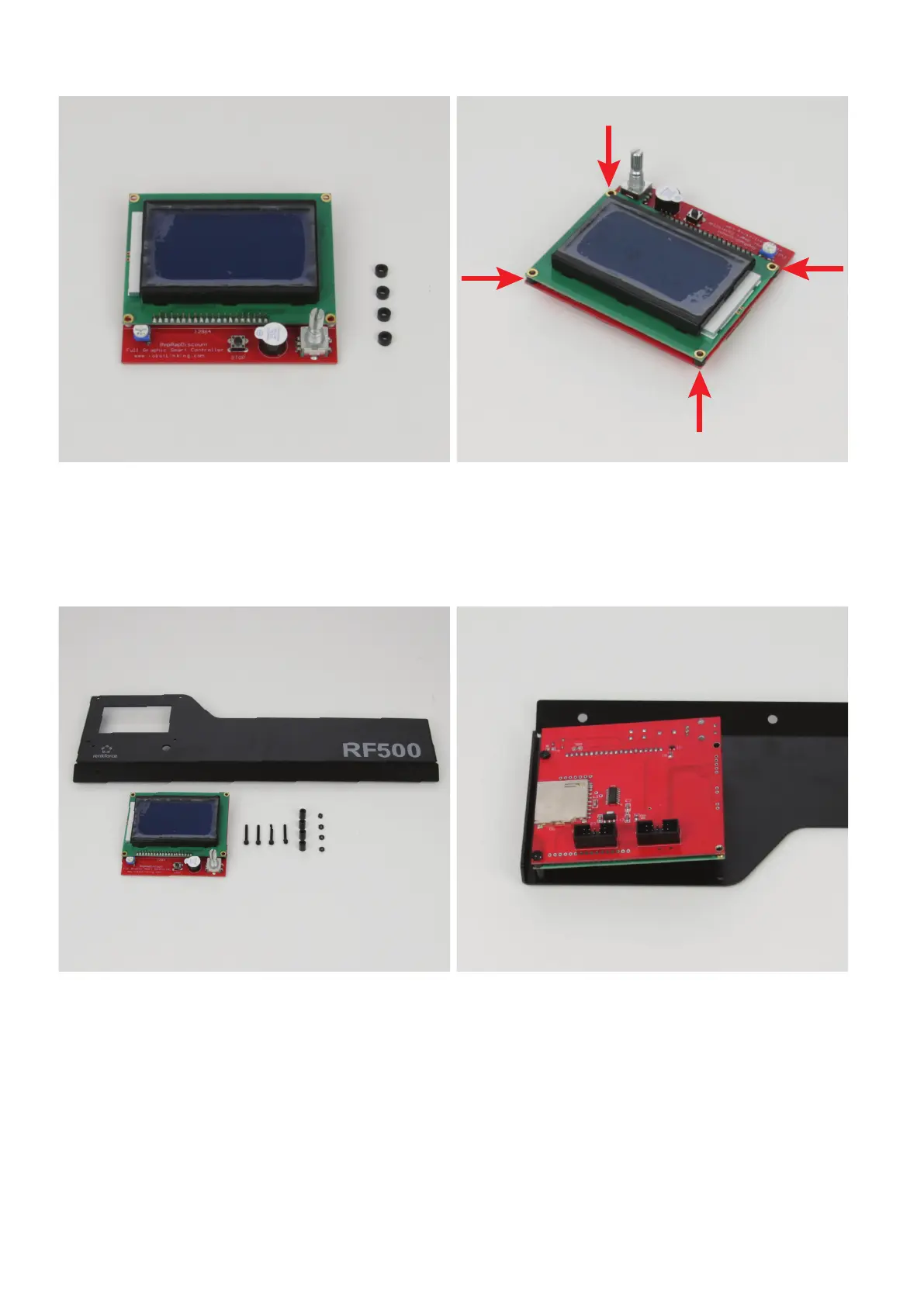
1x display
4xspacer3mm(diameterinside3mm)
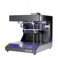
Push one spacer between the display and control PCB in each at-
tachment hole.
Align the spacer precisely with the holes.
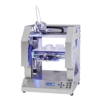
Installationofthedisplayinthedisplayholder
1x display holder
1x display
4x cylinder head screw M2.5x20 black
4xspacer9mm(diameterinside3mm)
4x nut M2.5 black
Removethelmfromthedisplayrst.
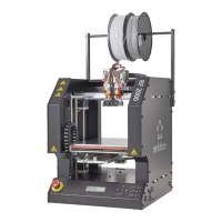
Attach the display to the display holder from the inside. The dial switch
must be guided through the corresponding opening.
Start at the outside.
Install the screws one at a time. After inserting a screw, secure it with
a nut.
The sequence from the outside is:
Cylinder-head screw - display holder - spacer 9 mm - display
(withspacer3mm)-nut