Home Setup
34
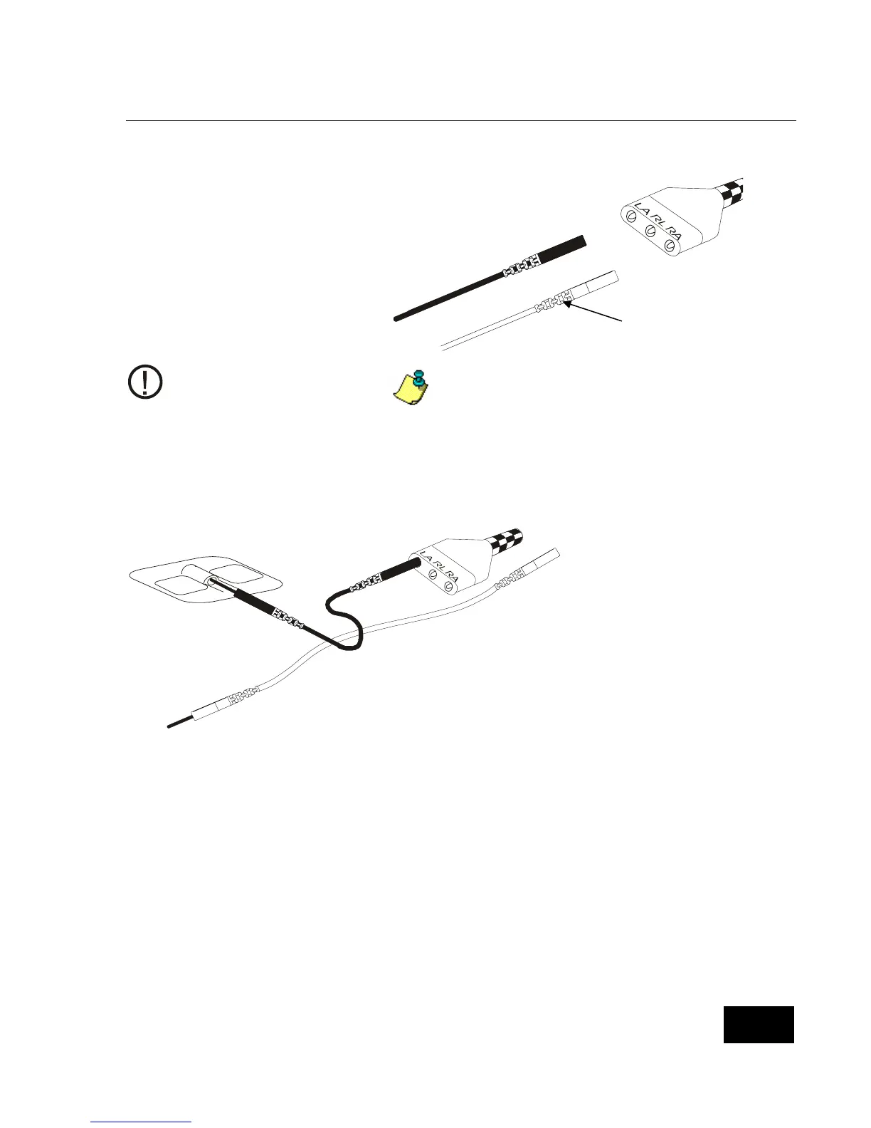
Step 3: Connect the Lead Wires to the Patient Cable.
The larger end of the patient cable has
three openings, marked LA (black), RL
(green), and RA (white).
Take the white lead wire and
insert it into the opening marked
RA.
Take the black lead wire and
insert it into the opening marked
LA.
Firmly push each lead wire in until
the socket snaps into place.
When you need to remove a
lead wire, grasp and pull at the
strain relief area located near
the connecting tip. Do not
grasp the wire.
Use of the third (green - RL) electrode and
lead wire is normally not required, but may
help reduce excessive false low heart rate
alarms.
Step 4: Connect the Lead Wires to the Electrodes.
Insert the black LA
lead wire into one
electrode.
Insert the white RA
lead wire into the
other electrode.
Make sure the metal
tips of the lead wires
are fully inserted into
the electrodes.
Strain Relief
rea.