13-6 Application Instructions Synchronous Motors MKD
19.05.2004 Version7.0 DOK-MOTOR*-MKD*******-PR07-EN-P
13.3 Design and Installation Positions
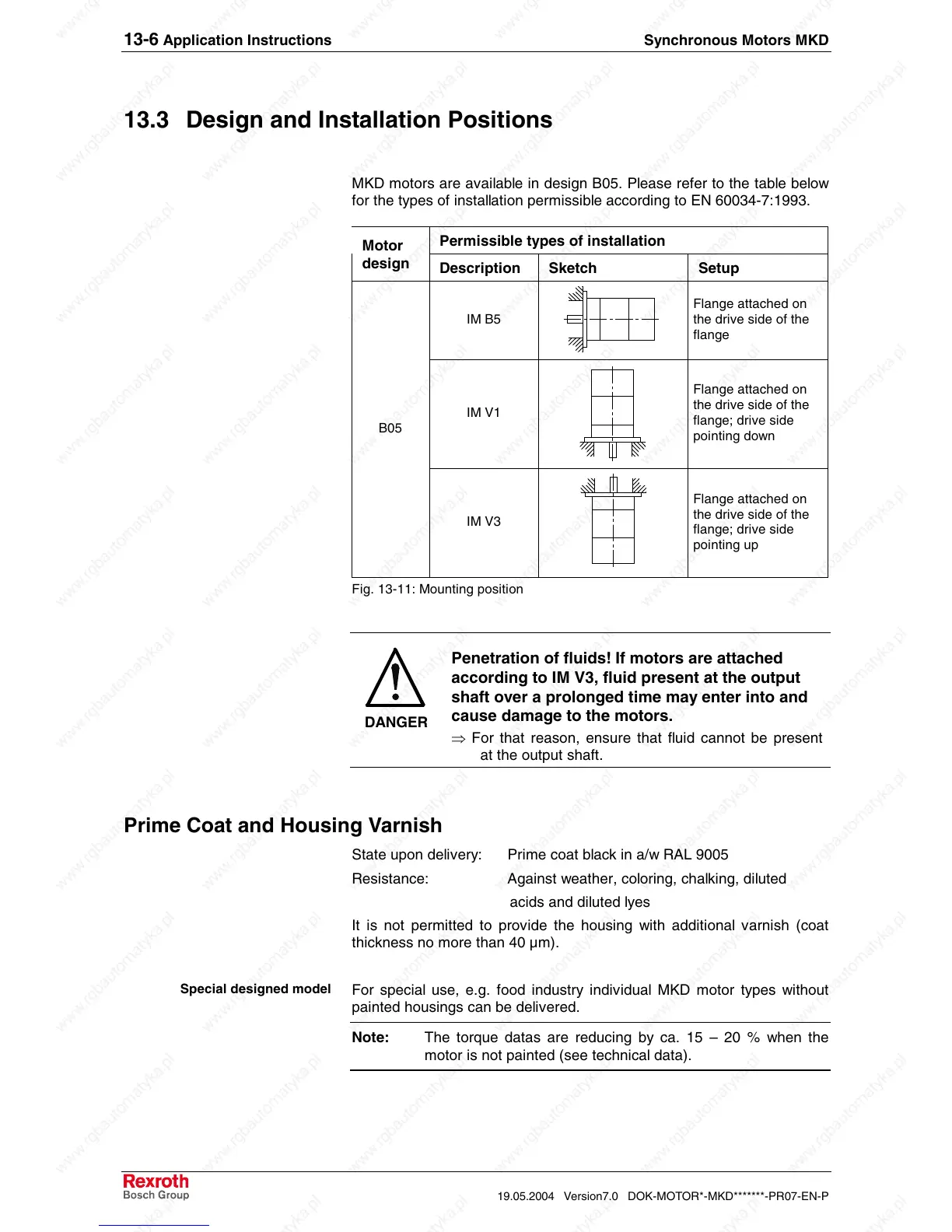
MKD motors are available in design B05. Please refer to the table below
for the types of installation permissible according to EN 60034-7:1993.
Permissible types of installation
Motor
design
Description Sketch Setup
IM B5
Flange attached on
the drive side of the
flange
IM V1
Flange attached on
the drive side of the
flange; drive side
pointing down
B05
IM V3
Flange attached on
the drive side of the
flange; drive side
pointing up
Fig. 13-11: Mounting position
DANGER
Penetration of fluids! If motors are attached
according to IM V3, fluid present at the output
shaft over a prolonged time may enter into and
cause damage to the motors.
⇒ For that reason, ensure that fluid cannot be present
at the output shaft.
Prime Coat and Housing Varnish
State upon delivery: Prime coat black in a/w RAL 9005
Resistance: Against weather, coloring, chalking, diluted
acids and diluted lyes
It is not permitted to provide the housing with additional varnish (coat
thickness no more than 40 µm).
For special use, e.g. food industry individual MKD motor types without
painted housings can be delivered.
Note: The torque datas are reducing by ca. 15 – 20 % when the
motor is not painted (see technical data).
Special designed model
 Loading...


