Synchronous Motors MKD MKD025 6-9
DOK-MOTOR*-MKD*******-PR07-EN-P Version7.0 19.05.2004
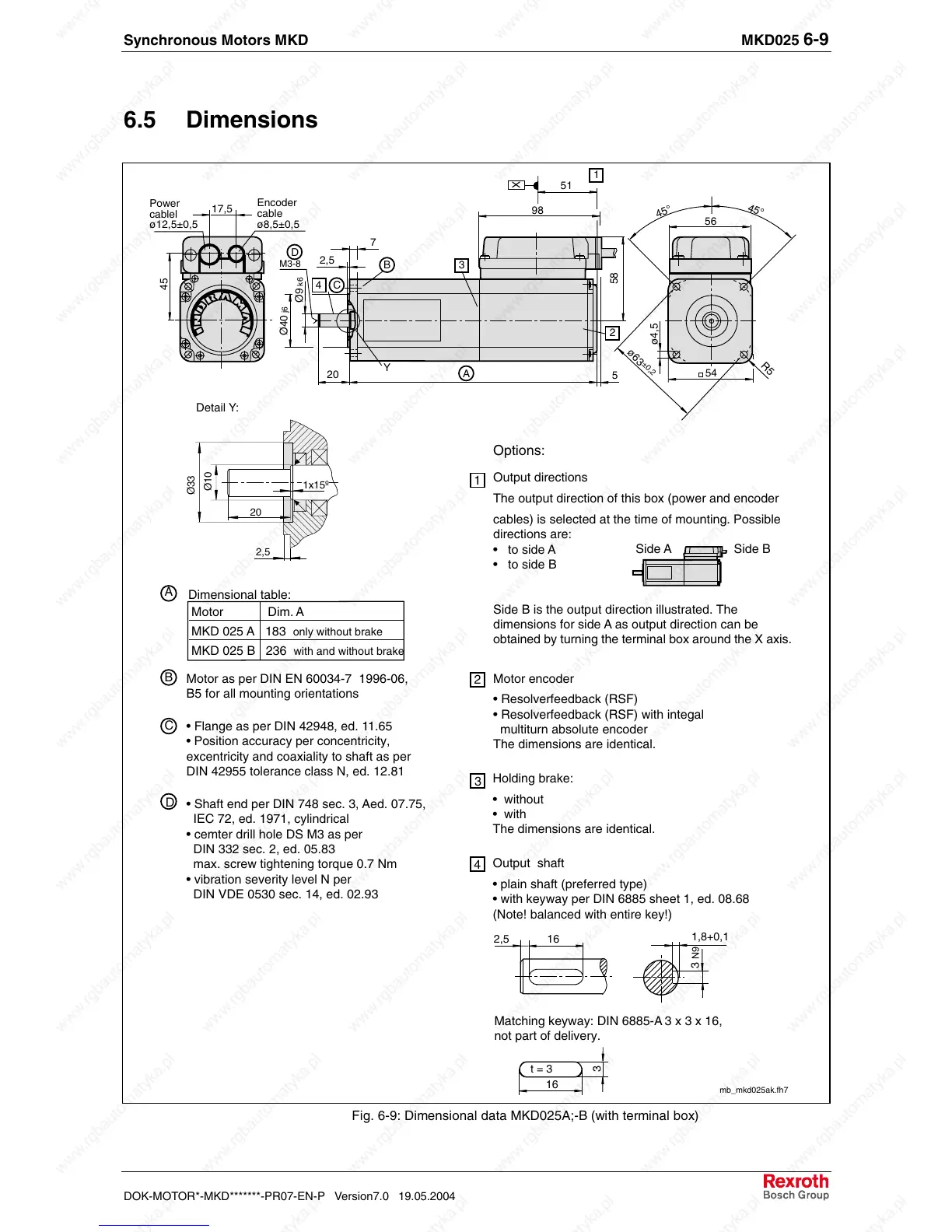
6.5 Dimensions
Dimensional table:
D
B
C
mb_mkd025ak.fh7
16
1,8+0,1
3
N9
Options:
Holding brake:
• without
• with
The dimensions are identical.
Output shaft
• plain shaft (preferred type)
• with keyway per DIN 6885 sheet 1, ed. 08.68
(Note! balanced with entire key!)
Matching keyway: DIN 6885-A 3 x 3 x 16,
not part of delivery.
2,5
Motor encoder
• Resolverfeedback (RSF)
• Resolverfeedback (RSF) with integal
multiturn absolute encoder
The dimensions are identical.
Output directions
The output direction of this box (power and encoder
cables) is selected at the time of mounting. Possible
directions are:
• to side A
• to side B
Side B is the output direction illustrated. The
dimensions for side A as output direction can be
obtained by turning the terminal box around the X axis.
2
1
3
4
16
3
t = 3
A
Motor as per DIN EN 60034-7 1996-06,
B5 for all mounting orientations
• Flange as per DIN 42948, ed. 11.65
• Position accuracy per concentricity,
excentricity and coaxiality to shaft as per
DIN 42955 tolerance class N, ed. 12.81
• Shaft end per DIN 748 sec. 3, Aed. 07.75,
IEC 72, ed. 1971, cylindrical
• cemter drill hole DS M3 as per
DIN 332 sec. 2, ed. 05.83
max. screw tightening torque 0.7 Nm
• vibration severity level N per
DIN VDE 0530 sec. 14, ed. 02.93
X
51
1
98
56
45°
45°
58
54
R5
ø4,5
ø63
±
0,2
2
5
20
7
2,5
Ø40 j6
Ø9 k6
17,5
45
C
M3-8
4
D
B
3
Encoder
cable
ø8,5±0,5
Power
cablel
ø12,5±0,5
Y
Side A Side B
A
Detail Y:
Ø10
Ø33
1x15º
20
2,5
Motor Dim. A
MKD 025 A 183
only without brake
MKD 025 B 236
with and without brake
Fig. 6-9: Dimensional data MKD025A;-B (with terminal box)
 Loading...


