13-10 Application Instructions Synchronous Motors MKD
19.05.2004 Version7.0 DOK-MOTOR*-MKD*******-PR07-EN-P
13.6 Output Shaft and Motor Bearing
Plain shaft
The standard design recommended for MKD motors provides a friction-
locked shaft-hub connection without play and excellent running
smoothness. Use clamping sets, clamping sleeves or clamping elements
to couple the machine elements to be driven.
Output shaft with key
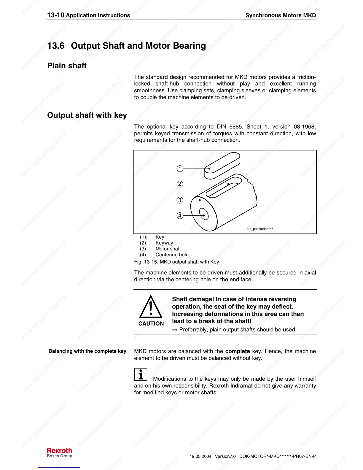
The optional key according to DIN 6885, Sheet 1, version 08-1968,
permits keyed transmission of torques with constant direction, with low
requirements for the shaft-hub connection.
1
2
3
4
nut_passfeder.fh7
(1): Key
(2): Keyway
(3): Motor shaft
(4): Centering hole
Fig. 13-15: MKD output shaft with Key
The machine elements to be driven must additionally be secured in axial
direction via the centering hole on the end face.
CAUTION
Shaft damage! In case of intense reversing
operation, the seat of the key may deflect.
Increasing deformations in this area can then
lead to a break of the shaft!
⇒ Preferrably, plain output shafts should be used.
MKD motors are balanced with the complete key. Hence, the machine
element to be driven must be balanced without key.
Modifications to the keys may only be made by the user himself
and on his own responsibility. Rexroth Indramat do not give any warranty
for modified keys or motor shafts.
Balancing with the complete key
 Loading...


