15-8 Assembly Synchronous Motors MKD
19.05.2004 Version7.0 DOK-MOTOR*-MKD*******-PR07-EN-P
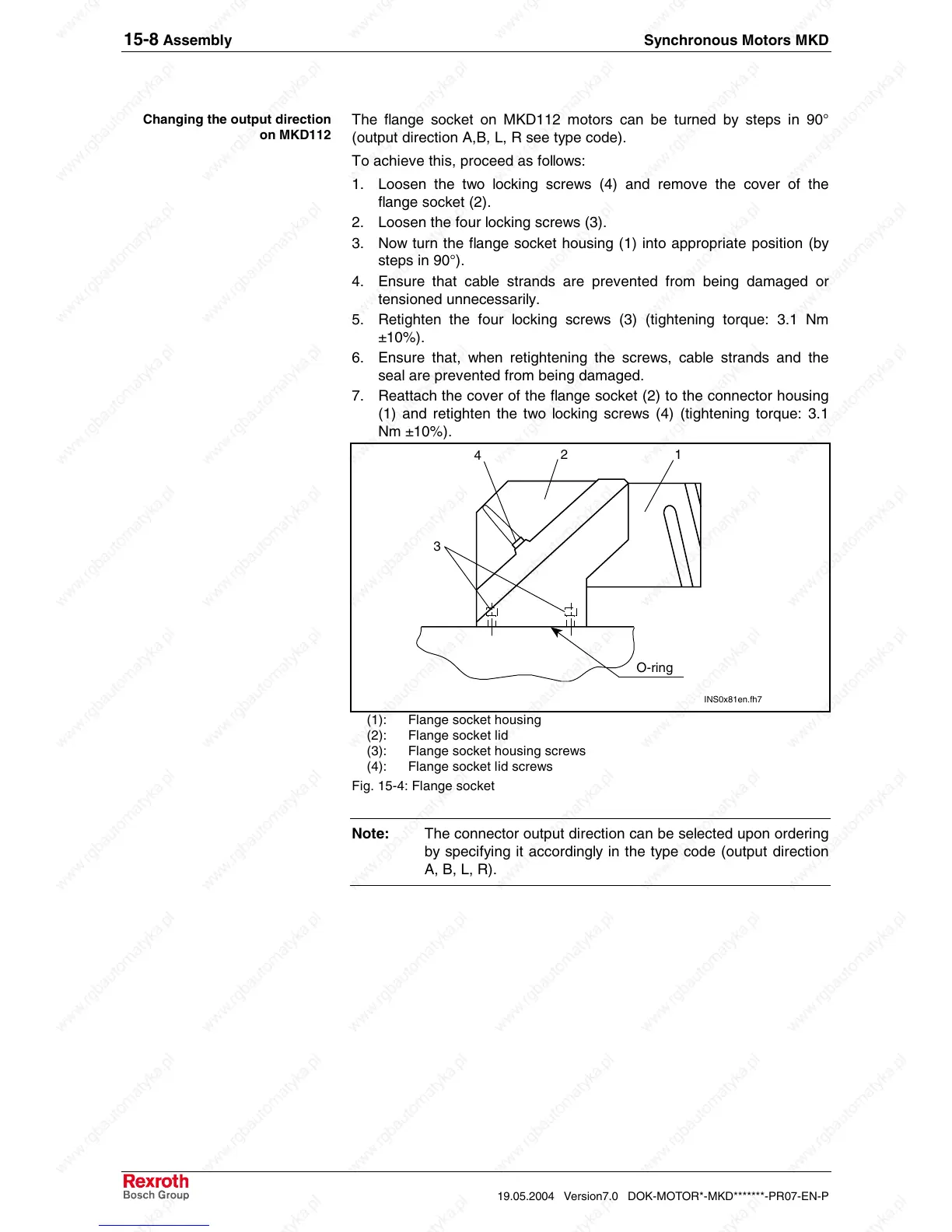
The flange socket on MKD112 motors can be turned by steps in 90°
(output direction A,B, L, R see type code).
To achieve this, proceed as follows:
1. Loosen the two locking screws (4) and remove the cover of the
flange socket (2).
2. Loosen the four locking screws (3).
3. Now turn the flange socket housing (1) into appropriate position (by
steps in 90°).
4. Ensure that cable strands are prevented from being damaged or
tensioned unnecessarily.
5. Retighten the four locking screws (3) (tightening torque: 3.1 Nm
±10%).
6. Ensure that, when retightening the screws, cable strands and the
seal are prevented from being damaged.
7. Reattach the cover of the flange socket (2) to the connector housing
(1) and retighten the two locking screws (4) (tightening torque: 3.1
Nm ±10%).
O-ring
3
4
2
1
INS0x81en.fh7
(1): Flange socket housing
(2): Flange socket lid
(3): Flange socket housing screws
(4): Flange socket lid screws
Fig. 15-4: Flange socket
Note: The connector output direction can be selected upon ordering
by specifying it accordingly in the type code (output direction
A, B, L, R).
Changing the output direction
on MKD112
 Loading...


