Tech Service Bulletin No. A172/A199 – 016
Page 5 of 17
4.
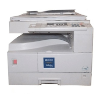
Connect a meter, black lead to frame ground, red lead to the grid connector on the C/G Power Pack.
Set the meter to read DC voltage greater than 400 volts as pictured:
5.
Make a single color (black) copy and observe that the meter indicates -400 volts.
6.
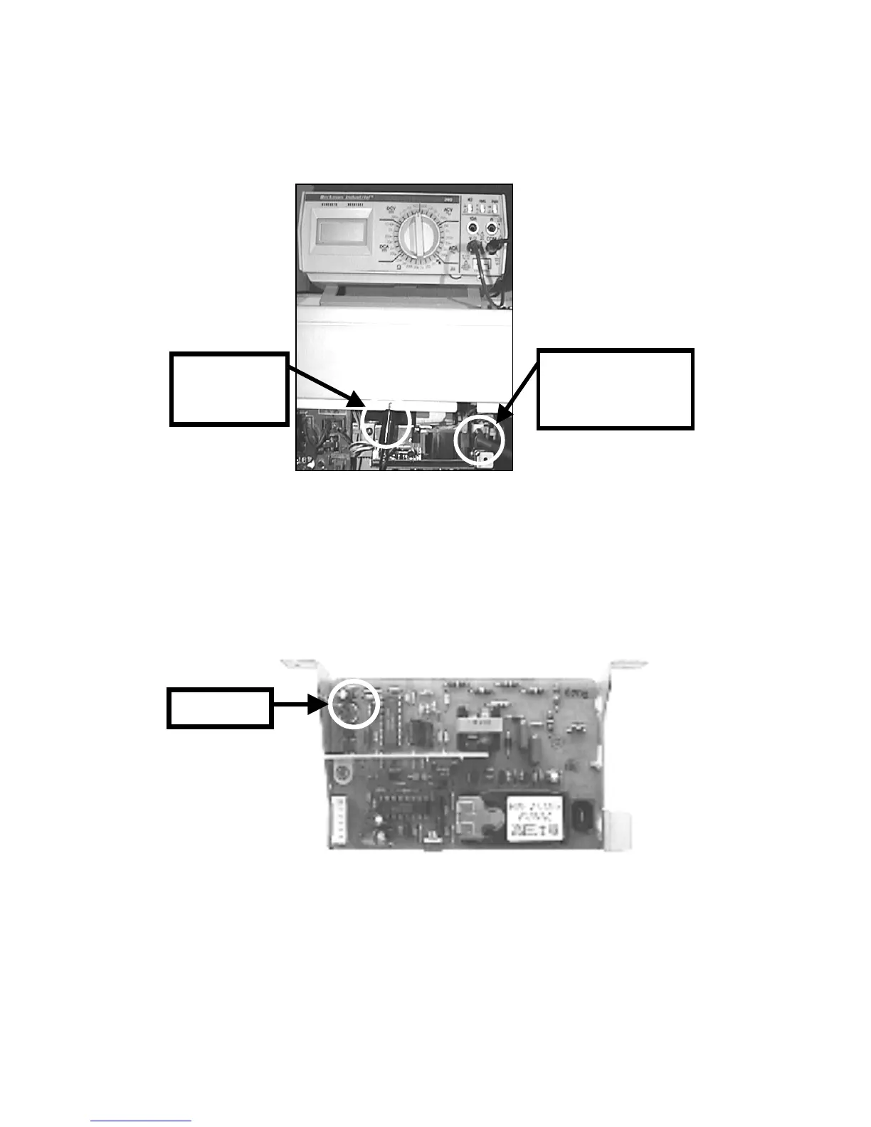
If adjustment is required, adjust VR G on the C/G Power Pack as pictured below.
NOTE:
It is necessary to slightly / reposition the C/G Power Pack to adjust this VR.
When adjustment is complete, reset all SP modes to previous settings (Auto Process Control to “PID” & VG
for Black to original setting).
NOTE:
If the adjustment cannot be achieved, leave the SP setting as specified on the first page of this
procedure (confirming charge grid) and proceed to the next page for checking the Grid PWM signal.
Continued…
0#733
Black meter
lead to frame
ground
Red meter lead to
grid CN, behind the
black HV
transformer
VR-G
 Loading...