Tech Service Bulletin No. A172/A199 – 016
Page 6 of 17
•
Charge Grid PWM Check Procedure
NOTE:
Before proceeding with these checks, confirm that the SP Modes are set as
specified on page 4 of 17 and set your meter to greater than 5VDC.
1.
Check CN 504 - A14, on the Main Board for approximately 5.02 volts while making a single color (black)
copy. If the voltage is not within this range, replace the Main Board. If this check is normal, proceed to
the next step.
2.
Check CN 701 - A1, on Interface Board - 1 while making a single color (black) copy. Confirm that the
voltage level is approximately the same voltage as above (5.02VDC). If the voltage is not within this range,
replace or repair the harness between the Main Board and Interface Board - 1. If this check is normal,
proceed to the next step.
3.
Check CN 709 - B5 on Interface Board - 1 while making a single color (black) copy confirm that the
voltage level is approximately the same voltage as above (5.02VDC). If the voltage is not within this
range, replace Interface Board - 1
VG Set To
PWM at CN 504 - A14
CN 701 - B5
CN 709 - B5
-400 5.02
-500 4.13
-600 3.29
-700 2.46
-800 1.62
NOTE:
If one of the components above is found defective, replace the part then confirm Charge Grid
voltage by following the procedure on page 4of 17 and page 5 of 17 (Confirming Charge Grid).
When adjustment is complete, reset all SP modes to previous settings
(Auto Process Control to “PID” & VG for Black to original setting).
If the indicated voltage cannot be achieved, replace the following parts:
1.
DC Power Pack - C\G - AZ300042.
2.
Charge Corona Unit - AD004087.
3.
Charge Corona Receptacle - A1092300.
Continued…
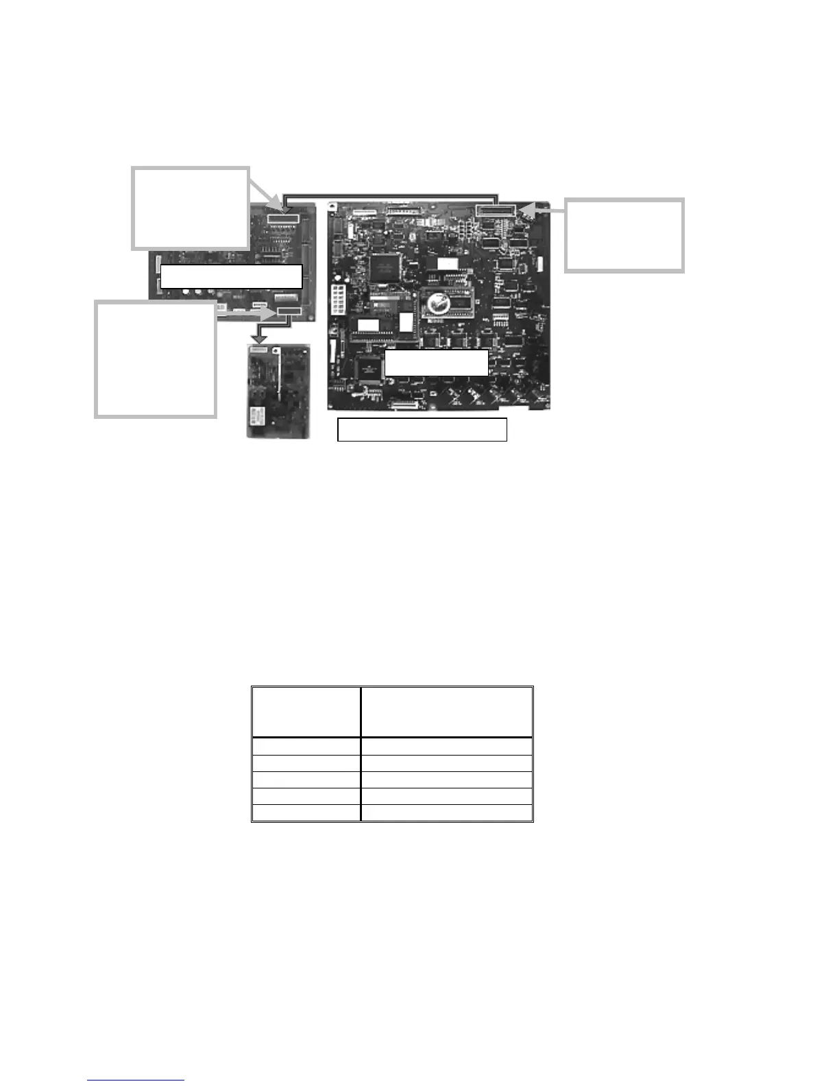
Charge Grid PWM circuit
CN 504-A14
Grid PWM
Signal from
Main Board
CN 701 - A1
Grid PWM
Signal from
Main Board
CN 709 - B5
Charge Grid
PWM output
from Interface
Board 1 to the
DC Power Pack
Main Board
Interface Board-1
NOTE:
-400 to -800 is
provided to illustrate PWM
range
 Loading...