Installaon opons for output shas
Refer to (if applicable):
• §4.5.1 for the (most) used connecons of basic output shafts to operated systems (installaon
opons A–F)
• §4.5.2 for the installaon opons (A–F) of special output shafts
• §4.5.3 for the installaon of chains onto sprockets (for installaon opons A–D)
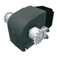
• §4.6 for TRA models with TRA drive-unit (installaon opons G, H, I)
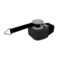
• §4.7 for L models with belt drum (installaon opon J)
• §4.8 for L models with cable drum (installaon opon K).
4.1 Special tools and equipment
No special tools or equipment are necessary to install, to connect or for commissioning.
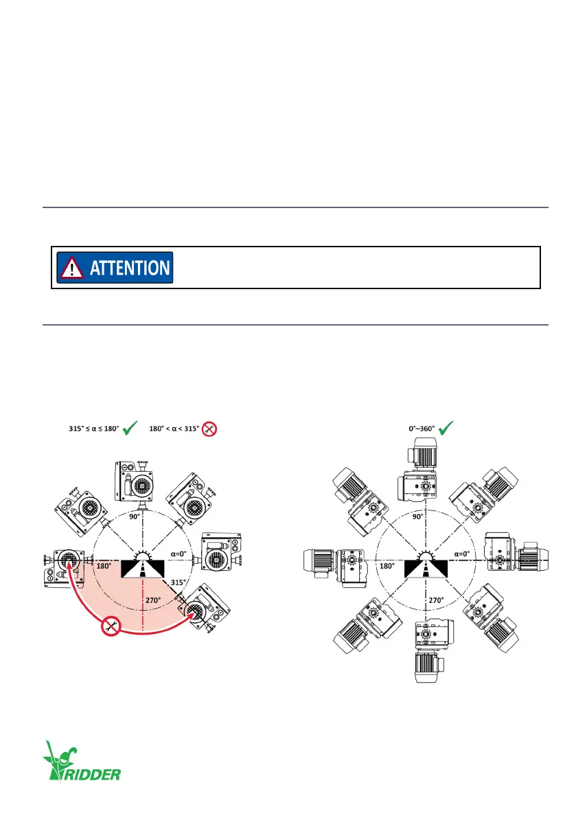
4.2 Mounng posions
• Refer to the illustraons and use only a permied mounng posion for installaon!
• After installation interchange the plug in the highest posion with the vent plug! This is not
applicable to motor gearboxes that are lled with grease!
RW45 [grease lubricaon]:
Make sure that the correct equipment and tools are used.
Ridder Drive Systems B.V.
T +31 (0)341 416 854 - F +31 (0)341 416 611 - I ridder.com
15