4.4 Installaon
The condions and starng points that follow are applicable for installaon. Make sure that the
working condions comply with the, local or naonal, laws and regulaons.
• Do not remove the product from the packaging unl a short me before the installaon.
• Use the correct work equipment and accessories (belts, chains, pallets or such) if it is not
permied or possible to put the product manually in posion.
• Only use a permied mounng posion when you install the RW motor-gearbox. Refer to §4.2.
• The mounng plates are available in dierent dimensions for dierent conguraons. Refer to
“Oponal mounng plates ❶”.
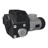
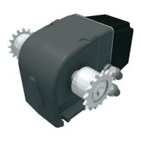
Install the RW motor-gearbox onto the mounng plate or an alternave (refer to “Oponal
mounng plates ❷”):
• With the supplied spring washers and bolts M10x20 (2x) for an RW45 drive unit
• With the supplied spring washers and bolts M10x25 (3x) for RW240–600 and RW70/140 drive
units
• With the supplied spring washers and bolts M12x25 (4x) for an RW800 drive unit.
Refer to “Minimum Screw-in depth (SID)” which also shows the standard bolt-installation (SBI).
• The RSU or RLS limit-switch system and other components (RPU and such) can give informaon
“in operaon” and/or during commissioning. Thus, easy access and a sasfactory view is
recommended for the locaon of the RW motor-gearbox.
• In the factory the reductor is lled with the necessary quanty of grease (usually only RW45) or
oil. Aer installaon interchange (of reductors lled with oil) the plug in the highest posion with
the vent plug! Refer to §4.2.
Ridder Drive Systems B.V.
T +31 (0)341 416 854 - F +31 (0)341 416 611 - I ridder.com
19