5
• Do steps 1 thru 4 again to adjust the opposite end posion (A or B).
• Go to step 6 if the two end posions are adjusted.
6
• The procedure to adjust the limit-switch system is completed.
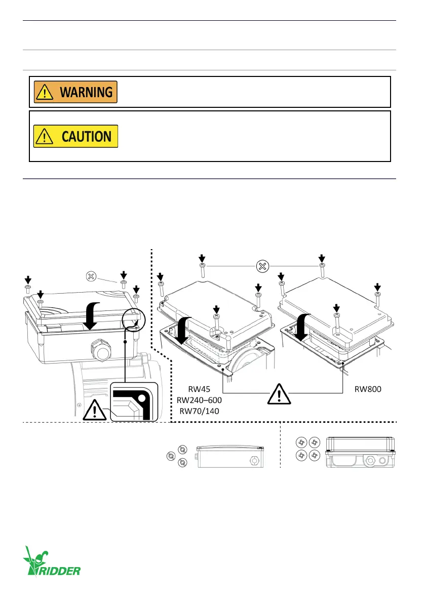
7.4 Installaon covers
Always put the covers (2x) and the bolts (2x4 [or 1x4 + 1x3]) back aer the work. Problems with
moisture and/or the IP protecon rang (if applicable) must be prevented!
• Do a check of the gaskets (2x) for dirt and damages.
• Put gaskets (if removed) back carefully and make sure that no damage is caused.
• Tighten the bolts crosswise and gradually with the correct ghtening torque (2x4 [or 1x4 + 1x3]).
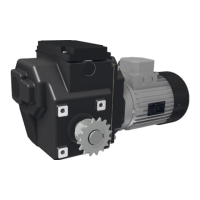
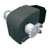
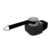
In this manual shown illustraons can be dierent than the components and/or systems.
Do a funconal check of the limit-switch system aer the two end
posions are adjusted.
Do not go across adjusted end posions when the motor gearbox
is operated manually or with electric tools (externally with the
hexagon socket in the electric-motor sha).
This prevents damage to the limit-switch system and an incorrect
funconal operaon.
PH/PZ - 0.5 Nm (4x)
PH2 - 1.5 Nm (4x)Plasc cover *
TX\SLOT (3x) - 1.0 Nm
* Alternaves: Metal cover
PH/(PZ) (4x) - 1.0 Nm
Ridder Drive Systems B.V.
T +31 (0)341 416 854 - F +31 (0)341 416 611 - I ridder.com
46