7.3 Adjusng the end posions
The condions and starng points that follow are applicable:
• The direcon-of-rotaon of the motor gearbox is correct aer connecon in §5.5–§5.8.
• The switching sense of the RLS/RSU is correct aer connecon in §5.5–§5.8.
• Adjusng sequence: You can adjust the end posions from A to B or from B to A.
Note: Refer to §5.9 “Change Direcon-of-rotaon - Switching sense”.
u
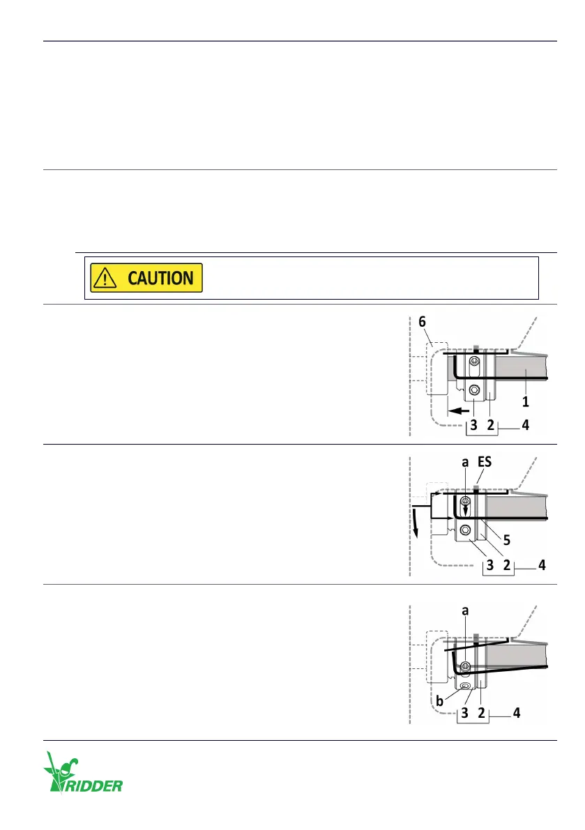
Descripon
1
Refer also to §6.2 “Direcon-of-rotaon RW motor-gearboxes” for the steps that follow.
1. Let the motor gearbox turn in the direcon A or B.
2. Do a check to see which duty switch (ES11 or ES12) is related to direcon A or B.
3. Let the system stop at an end posion (A or B).
Do not go across the limits of the system. This prevents
damage or injury.
2
Of the related limit switch (A or B):
1. Turn the knurled nut (2), on the threaded sha (1), in the
direcon of the stopper (6).
2. Tighten the knurled nut (2) with your hand against the
stopper (6).
3
1. Turn the adjusng ring (3) in the opposite direcon of
the knurled nut (2). The adjusng screw (a) and switching
spring (5) must operate the duty switch ES (ES11 or ES12).
2. Hold the adjusng ring (3) at this posion and go to step 4.
4
To lock the adjusng ring (3) on the knurled nut (2) with the
hex wrench 2 mm (7):
1. Tighten the long adjusng screw (a) with a ghtening
torque of 0.5–0.6 Nm.
2. Tighten the short adjusng screw (b) with a ghtening
torque of 0.5–0.6 Nm.
3. Tighten the long adjusng screw (a) again with a ghtening
torque of 0.5–0.6 Nm.
The adjusng ring (3) cannot turn freely at this me.
Ridder Drive Systems B.V.
T +31 (0)341 416 854 - F +31 (0)341 416 611 - I ridder.com
45