RLS/RSU CONTROL-CIRCUIT CONNECTION:
Current (I) in the control circuit
The limit-switch system is applicable for the currents that follow:
• 45 mA–130 mA at 24 V AC/DC
• A maximum of 100 mA at 115/230/240 V.
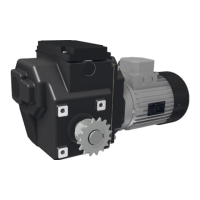
RW45 - RLS MOTOR-CURRENT CONNECTION:
Switching capacity of the limit switch at 115/230/240 V AC
A motor-gearbox with a 1-phase electric motor of:
• Maximum 0.09 kW at 115 V AC - 60 Hz or 230 V AC - 50 Hz
• Maximum 0.11 kW at 240 V AC - 60 Hz.
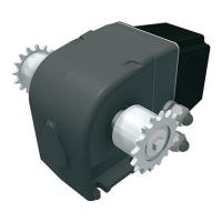
RW241/242 - RLS MOTOR-CURRENT CONNECTION:
Switching capacity of the limit switch at 115/230/240 V AC
A motor-gearbox with a 1-phase electric motor of:
• Maximum 0.18 kW at 115 V AC - 60 Hz or 230 V AC - 50 Hz
• Maximum 0.22 kW at 240 V AC - 60 Hz.
CONNECTIONS AND FUNCTIONAL OPERATION
The RLS limit-switch system has two connecon blocks. Each connecon block has three connecon
terminals. The RSU limit-switch system has a connecon block with twelve connecon terminals.
• Starng point for a correct connecon and funconal operaon is the wiring diagram in §5.5/§5.6
(RLS) or §5.7/§5.8 (RSU).
• Connecon of all safety switches and duty switches is mandatory.
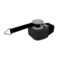
WORKING PRINCIPLE
• The gearbox operates the threaded sha (1) of the limit-switch system through a transmission.
• The connecon nuts (4) move linearly along the threaded sha (1).
• One adjusng screw (a) touches the switching spring (5).
• When a connecon nut (4) is at the end posion, it touches the stopper (6) and subsequently will
turn with the threaded sha (1).
• The adjusng screw (a) moves the switching spring (5) which operates the duty switch (ES11 or
ES12). The motor gearbox stops.
• If a failure of the duty switch occurs, the switching spring (5) operates the safety switch (ES21 or
ES22). This makes sure the motor gearbox stops. It prevents consequenal damage to the system.
Ridder Drive Systems B.V.
T +31 (0)341 416 854 - F +31 (0)341 416 611 - I ridder.com
44