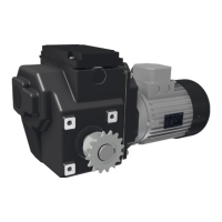
5.9 Change Direcon-of-rotaon - Switching sense
If necessary, it is possible to change the direcon-of-rotaon and/or the switching sense. Refer to
§6.2, §7.2 and §7.3.
Wiring diagram §5.5–5.6 [RLS]: RW45\RW241/242
Wiring diagram §5.7–5.8 [RSU]: RW243/245/400/600\RW800\RW70/140
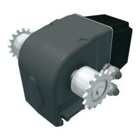
5.10 OPTIONAL - Posion Feedback
You can connect a digital posioning-meter (RPU) or a Ridder Potentiometer installaon set to the
RW motor-gearbox. Refer to the product-manuals at ridder.com for the installaon and connecons.
6. USER INSTRUCTIONS
If work becomes necessary when you use the drive unit (normal operaon), approved personnel
usually must do the work.
6.1 Usage - Condions and starng points
The condions and starng points that follow are applicable when you use the RW motor-gearbox.
Automac Control
Change direcon-of-rotaon:
Interchange V1 and W1 on the terminal block (EM).
Change switching sense:
Interchange 1 and 5 of the RLS.
Change direcon-of-rotaon:
Interchange V1 and W2 on the terminal block (EM).
Change switching sense:
Interchange 1 and 7 of the RSU.
The motor can start and stop automacally without a warning.
Persons can be in danger of life if they touch a system that is in
operaon.
Ridder Drive Systems B.V.
T +31 (0)341 416 854 - F +31 (0)341 416 611 - I ridder.com
38