6.3 Operaon
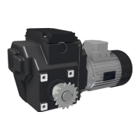
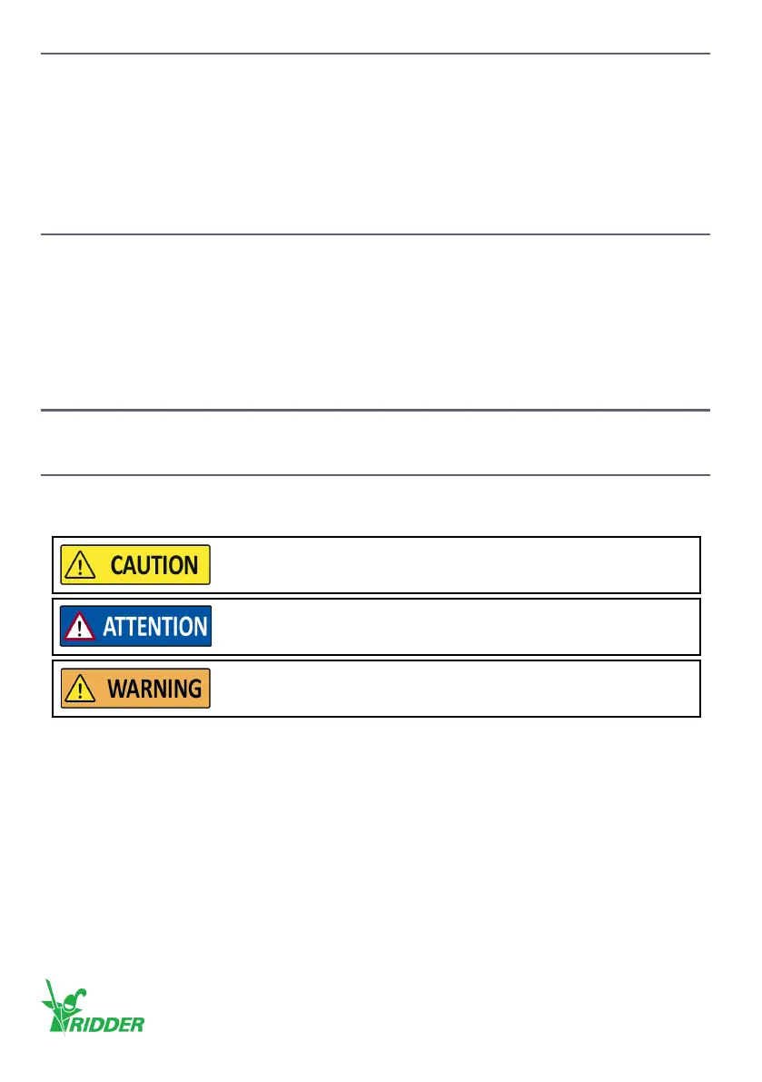
The RW motor-gearboxes are usually used in automated systems.
Operaon is possible with a manual control (MC) and/or other Ridder control components, which
are compable with (if applicable) “Automac Control-Systems” (ACS).
Refer to the Ridder catalog or website ridder.com for more informaon. Always refer to the related
informaon and manuals (ACS and control components).
6.4 Safety funcons and stop funcons
The RW motor-gearbox has the safety funcons and stop funcons that follow:
1. Stop at an adjusted end posion when a duty switch is operated
2. Stop when a safety switch is operated if a duty switch not disconnects
3. Stop when not operated and then lock the output sha because of a self-braking worm-gear
transmission
4. Thermal-overload protecon of the electric motor with a built-in PTO switch.
7. COMMISSIONING INSTRUCTIONS
The commissioning is only permied to approved personnel.
7.1 Commissioning - Condions and starng points
• It is important to fully know the working principle of the RLS/RSU limit-switch system in §7.2.
• Aer that obey the procedure in §7.3.
Do not go across the limits of the system. This prevents damage or
injury.
Before the system is put into operaon, the installer must always
make sure that the limit switch is correctly adjusted.
Make sure that there is no blockage of the system before the limit-
switch system is adjusted. This prevents damage or injury.
Ridder Drive Systems B.V.
T +31 (0)341 416 854 - F +31 (0)341 416 611 - I ridder.com
42