Mains-voltage loop-connecon
If a mains-voltage loop-connecon is used, make sure that connecon terminals, plug connectors
and cables are sucient for the permied current load. If you do not obey this instrucon thermal
damage to components or adjacent objects can occur.
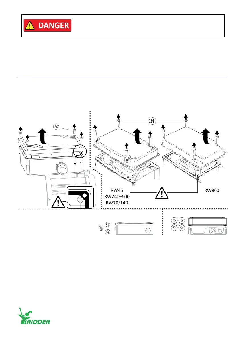
5.1 Removal covers
• Remove the bolts (2x4 [or 1x4 + 1x3]) and the covers (2x) temporarily to do all necessary work.
The gaskets (2x) usually stay in their posion.
• Make sure that no damage is caused to the gaskets and that they do not become dirty.
• Install the covers (2x) again aer the work! Refer to the end of chapter 7.
In this manual shown illustraons can be dierent than the components and/or systems.
The power supply of the motor gearbox can directly or not directly
put the drive unit into movement. This can also cause an electric
shock which can kill you if electrical components are touched.
PH/PZ (4x)
PH2 (4x)Plasc cover *
TX\SLOT (3x)
* Alternaves: Metal cover
PH/(PZ) (4x)
Ridder Drive Systems B.V.
T +31 (0)341 416 854 - F +31 (0)341 416 611 - I ridder.com
29