4.6 TRA drive-unit onto RW45\240TRA motor gearbox
Installation options G, H, I
G: Type A mounng plate installed between the motor gearbox and the TRA drive-unit.
Refer to §4.4: “Oponal mounng plates”, step ❶A.
Do the steps ❶, ❷ + ❸, ❹, ❺ of the two illustrations that follow.
H: Foot mounng or top mounng of the on the motor gearbox installed TRA drive-unit.
Do the steps ❶, ❷ + ❹, ❺ + ❻ or ❼ of the two illustrations that follow.
I: Wall mounng with the special wall mounng plate (417910/417953) of the on the motor gearbox
installed TRA drive-unit.
Do the steps ❶, ❷ + ❹, ❺, ❽, ❾ of the two illustrations that follow.
Preparing components (G, H and I)
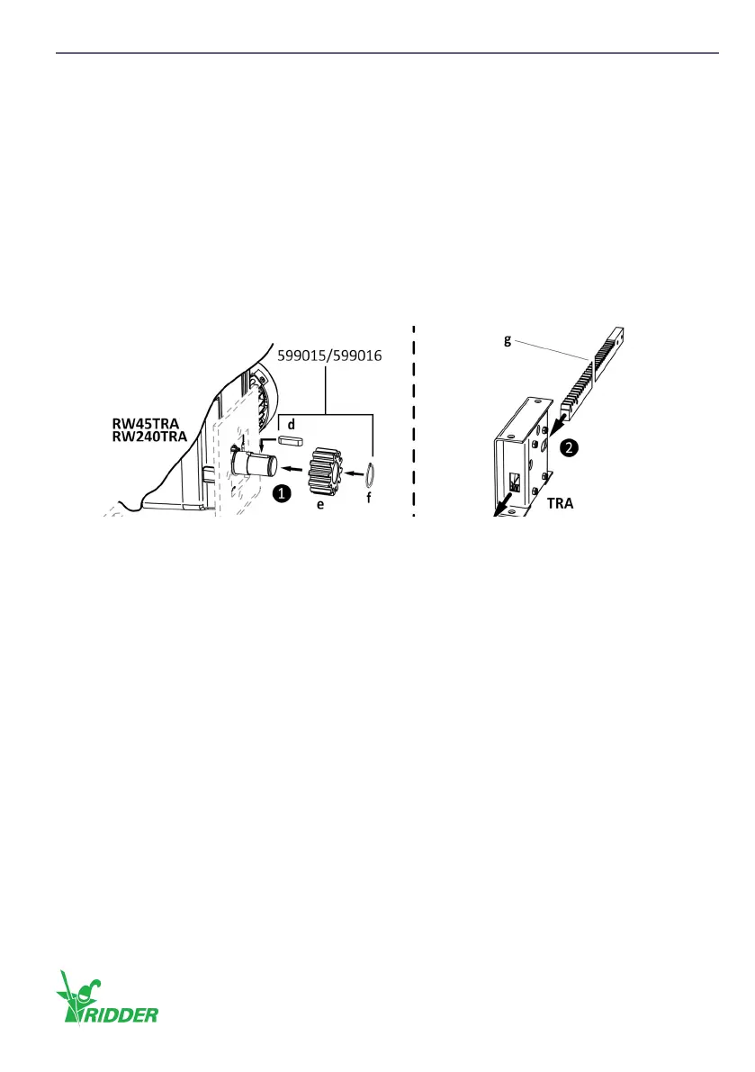
❶ Install the sha key (d), the pinion (e) and the retaining ring (f) onto the output sha.
❷ Put the rack (g) through the TRA rack drive-unit.
Installation option G
Note: Possibly there is no mounng plate installed to the structure at this me. Install a (type A)
mounng plate or an alternave to the structure rst.
Refer to §4.4: “Oponal mounng plates”, step ❶A.
❸ Put the (type A) mounng plate (h) or an alternave between the gearbox and the TRA drive-
unit.
❹ Install the TRA rack drive-unit onto the gearbox (and mounng plate or alternave [h]) with the
special M10 bolts ([i] 599015/599016).
❺ Tighten the bolts (i) gradually with the correct ghtening torque. Refer to SID/SBI informaon.
Installation option H
❹ Install the TRA rack drive-unit onto the gearbox with the special M10 bolts ([i] 599015/599016).
❺ Tighten the bolts (i) gradually with the correct ghtening torque. Refer to SID/SBI informaon.
❻/❼ Drill two holes of Ø13mm for foot mounng (j) or top mounng (k) in the structure. Use
M12 fasteners (l or m) to install the TRA system onto the structure. Obey the instrucons
for installaon of M12 fasteners (l or m).
Ridder Drive Systems B.V.
T +31 (0)341 416 854 - F +31 (0)341 416 611 - I ridder.com
25