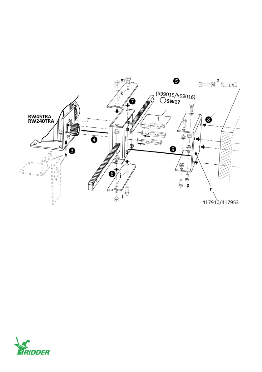
Installation option I
❹ Install the TRA rack drive-unit onto the gearbox with the special M10 bolts ([i] 599015/599016).
❺ Tighten the bolts (i) gradually with the correct ghtening torque. Refer to SID/SBI informaon.
❽ Install the wall mounng plate (n) onto the wall. Use four M10 fasteners ([o] wedge bolts or
such) for the wall mounng. Obey the instrucons for installaon of M10 fasteners ([o] wedge
bolts or such).
❾ Install the TRA drive-unit to the wall mounng plate (n) with four M10 bolts (p) and lock nuts.
Obey the instrucons for installaon of M10 fasteners (p).
The TRA520 rack-drives have zinc-plated racks with dierent lengths. Aach the racks to coupling-
plates, push-pull tubes, steel cables and/or such.
In this product manual shown illustraons can be dierent than the components and/or systems.
For more informaon on item numbers and models refer to the Ridder catalog or website at
ridder.com.
M12 (2x)
45 Nm
M12 (2x)
M10 (4x)
M10 (4x)
M10
(2x/3x)
Ridder Drive Systems B.V.
T +31 (0)341 416 854 - F +31 (0)341 416 611 - I ridder.com
26