2F-85 & 2F-140 - Instruction Manual
4.7.1.Connection Setup
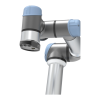
The following table describesthe connection requirements for controlling the gripper using the Modbus RTU protocol.
PROPRIETY DEFAULT VALUE
Physical Interface
RS-485
1
Baud Rate
2
115,200 bps
Data Bits 8
Stop Bit
2
1
Parity
2
None
Supported Functions
Read Input Registers (FC04)
Preset Multiple Register (FC16)
Master read & write multiple registers (FC23)
Exception Responses Not supported
Slave ID
2
0x0009 (9)
Robot Output / Gripper Input First Register 0x03E8 (1000)
Robot Input / Gripper Output First Register 0x07D0 (2000)
Termination Resistor
2
120 ohms
1
Various convertersare available in the Spare Parts, Kitsand Accessoriessection.
2
These parameters can be adjusted using the Robotiq User Interface.
Each register (word - 16 bits) of the Modbus RTU protocol is composed of 2 bytes (8 bits)from the gripper. The first gripper output
Modbus register(0x07D0) iscomposed from the first 2 Robotiq Gripper bytes (byte 0 and byte 1).
Info
200 Hzis the maximum speed when commanding / reading from the Robotiq Gripper. It is therefore recommended to
send commands with a minimum delay of 5 ms between them.
Info
Maximum baud rate of ACC-ADT-USB-RS485 is 115200 bps.
120 Ohmstermination resistor is already present on the converter and the gripper. If multiple grippers are connected in
parallel on the same RS485 cable, termination resistor must be set to OFF in communication parameters.
67