4.Control
Info
Unless specified, all valuesin thissection are hexadecimal values.
4.1.Overview
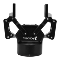
The Robotiq 2-Finger Adaptive Gripper iscontrolled directly via Modbus RTU using a RS485 signal.
Tip
To test variousgripper featuressuch asobject detection and force control, use the Robotiq User Interface. To download
it, go to support.robotiq.com, click on Select product > 2F-85 and 2F-140 Grippers> [anyrobot brand] > Software >
Robotiq User Interface > DOWNLOAD ZIP.
Since the Robotiq 2-Finger has itsown embedded controller, you can use high-level commands, such as " Go to requested
position" to control it.
Info
The operator can control force, speed and position of the gripper fingers.
l
Finger movement isalways synchronized.
l
Finger movement isinitiated via a single " Go to requested position" command.
l
Parallel or encompassing grip isperformed automatically.
l
Object detection is built-in. Operator isnotified after an object is picked once the " Go to" command has been
initiated. The feature also worksfor lost or dropped objects, and the user can be alerted if an object isdropped after
being detected.
l
In case of emergency, auto-release is engaged (open or close).
Control using registers
Grippers share their internal memory with the robot controller. One part of the memory isfor the robot output; gripper
functionalities. The other part of the memory is for the robot input; gripper status. Two typesof actionsare then available to a
robot controller:
1. Write in the robot output registers to activate functionalities;
2. Read in the robot input registers to get the statusof the gripper.
The Gripper Register Mapping section maps the registers used to control the gripper or to read its statuswhile the Robot Output
Registers& Functionalitiessection details the output (write) register functions, and the Robot Input Registers& Statussection
details the input (read) register status. The figure below is a representation of the memory and the control logic of the gripper. For
details, see the Control Logic Example section.
2F-85 & 2F-140 - Instruction Manual
47