Robotiq Hand-E Gripper - Instruction Manual
Maximum payload/External force vs. Custom finger design
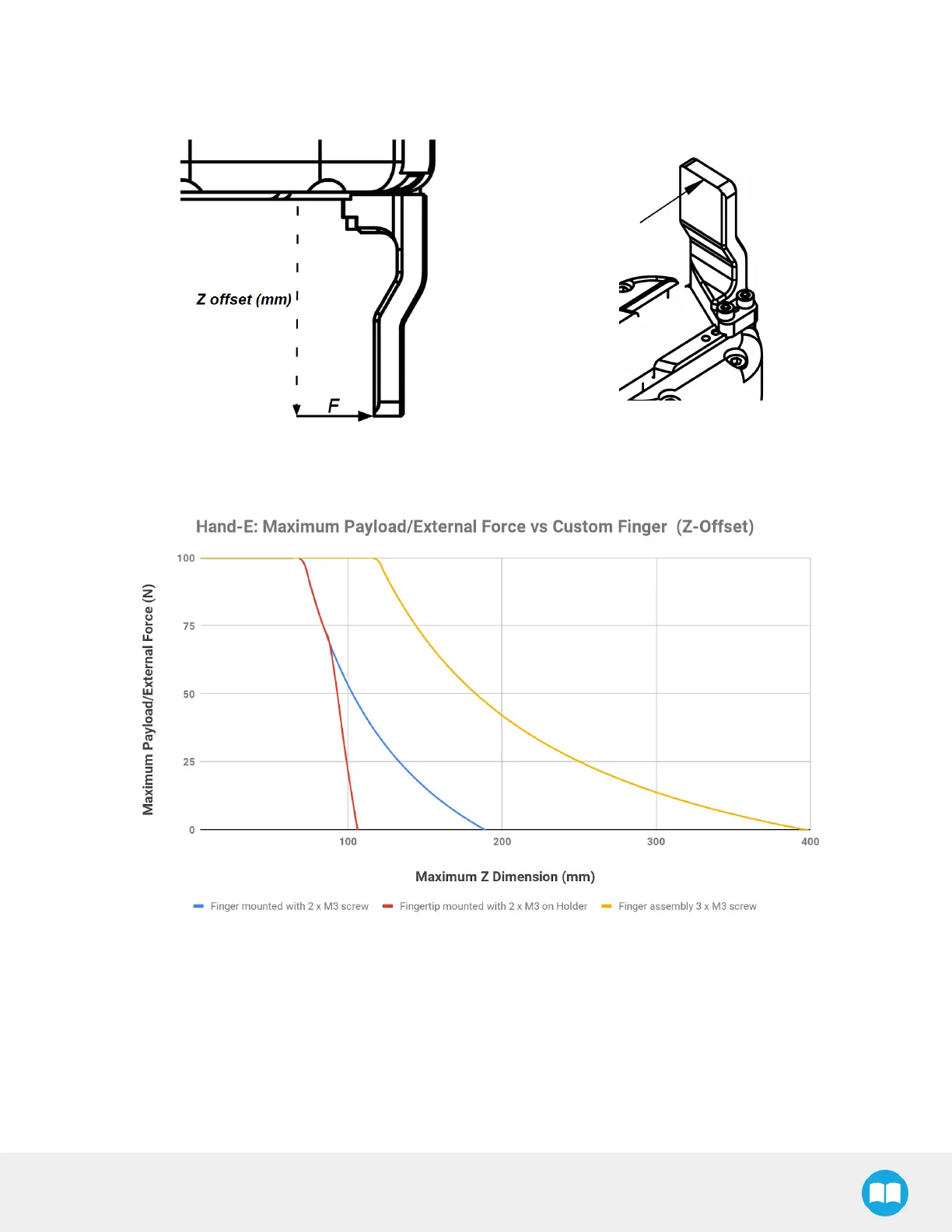
The maximum payload force recommended depends on the distance on the Z-axis at which the force/payload (F) is applied when using
custom fingers on the Hand-E Gripper.
Fig. 6-10: Z-axis offset at which force/payload is applied (tip of the finger, in the middle of the inner surface)
Fig. 6-11: Scheme Illustrating Maximum Payload/External Force vs. Z-Offset on Custom finger
l The blue curve in the graph represents the maximum force/payload (F) recommended at given Z offset for a custom finger design
mounted directly on the rack with two (2) M3 screws.
l The red curve in the graph represents the maximum force/payload (F)recommended at given Z offset for a custom finger design
mountend on a fingertip holder with two (2)M3 screws.
l The yellow curve in the graph represents the maximum force/payload (F) recommended at given Z offset for a custom finger design
mounted directly on the rack with three (3) M3 screws.
73