Robotiq Hand-E Gripper - Instruction Manual
3.5. Electrical Setup
Power and communication are established with the Hand-E Gripper via a single device cable. The device cable provides a 24V power
supply to the Gripper and enables serial RS485 communication to the robot controller.
Info
RS485 signals (485+, 485- and 485 GND) are isolated from the main 24V power supply. GND can be connected to any other
ground reference as long as the voltage potential between the grounds does not exceed 250V. Grounding reference is at the
user's discretion.
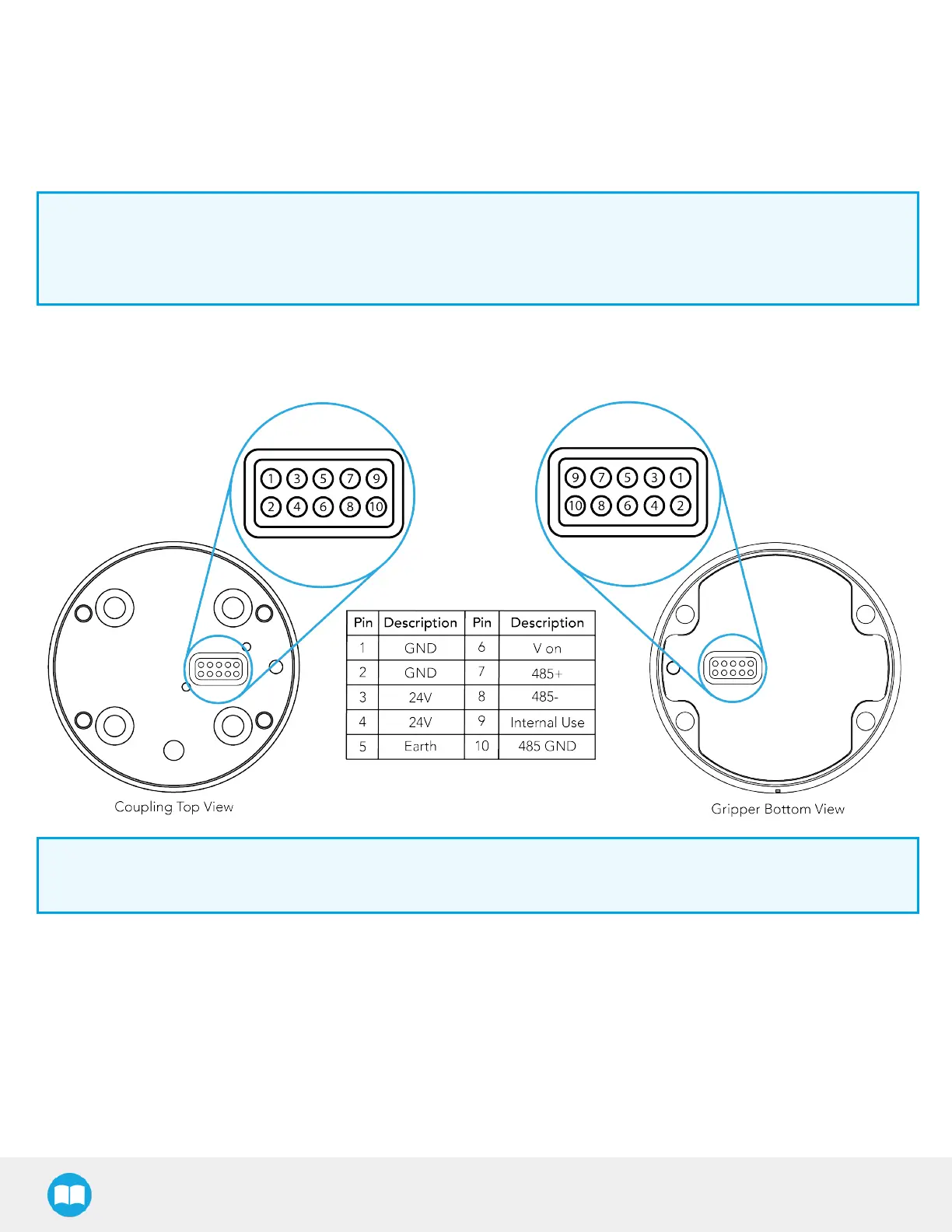
3.5.1. Pinout Interface
The Gripper interfaces with its coupling via a 10-spring pin connector located on its outer surface.
Info
The coupling used in the figure above is used for reference only and corresponds to bolt pattern ISO 9409-1-50-4-M6.
3.5.2. Coupling to controller
An optional Robotiq Universal Controller may be used between the Gripper and the network/robot controller if fieldbus communication
is required.
If a Robotiq Universal Controller is used, please refer to the instruction manual of the Robotiq Universal Controller. The figure below
represents the wiring scheme of the Hand-E Gripper with device cable, power supply, fuse (refer to the Required Tools and Equipment
section) and grounding.
21