46 Rockwell Automation Publication 2198-RM003B-EN-P - November 2020
Chapter 3 Connectors and Indicators
Kinetix 5100 Servo Drive
Connector Data
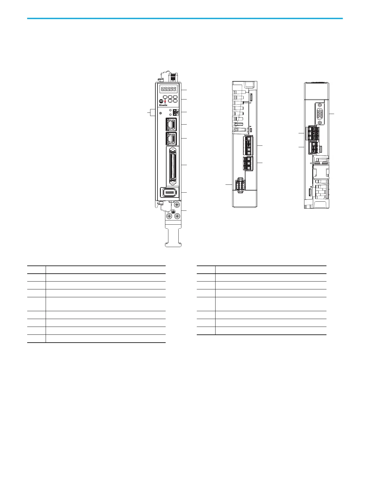
Use these illustrations to identify the connectors and indicators for Kinetix®
5100 servo drives.
Figure 15 - Features and Indicators (Catalog numbers 21998-E1004-ERS, 2198-E1007-ERS, and
2198-E1015-ERS)
1
4
5
6
7
8
9
3
2
13
11
14
15
12
10
L1 L2 L3
STO
MFB
L1C L2C P1 P2 DC-
2
1
I/0
AUX
5100
NET
MOD
CHARGE
U V W
DC+
ISH
ESH
Kinetix 5100 Drive, Bottom View
(2198-E1004-ERS drive is shown)
Kinetix 5100 Drive, Front View
(2198-E1004-ERS drive is shown)
Kinetix 5100 Drive, Top View
(2198-E1004-ERS drive is shown)
Table 45 - Features and Indicators Description (Cat. Nos. 2198-E1004-ERS, 2198-E1007-ERS, and 2198-E1015-ERS)
Item Description Item Description
1 Status display 9 Motor cable ground plate
2 Navigation push buttons 10 Safe Torque Off (STO) connector
3 Module, Network, and Charge status indicators 11 Mains input power connector
4 Mini USB connector 12
• Control power input (L1C and L2C) connections
• Reserved (P1, P2, and negative DC-bus) connections
5 Ethernet (PORT2) RJ45 connector 13 Motor feedback (MFB) connector
6 Ethernet (PORT1) RJ45 connector 14 Motor power output terminals
7 I/O signal connector 15 Shunt resistor terminals
8 Auxiliary feedback (AUX) connector

 Loading...


