Rockwell Automation Publication 2198-RM003B-EN-P - November 2020 51
Chapter 3 Connectors and Indicators
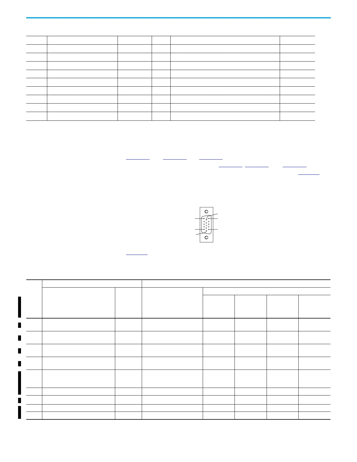
Motor Feedback Connectors This section describes the motor feedback connectors for the Ultra3000 drives
and the Kinetix 5100 drives. Both drives use15-pin connectors as shown in
Figure 21
. See Figure 12 and Figure 13 for locations of the Motor Feedback
connector on Ultra3000 drives. See Figure 15
, Figure 16, and Figure 18 for the
locations of the motor feedback connector on Kinetix 5100 drives. Table 48
describes and compares the signals that can be on the pins for each type of
drive.
Figure 21 - 15-Pin Motor Feedback Connector Pin Assignments
Table 48 compares the motor feedback connector pinouts for the Ultra3000
drive (CN2 connector) and Kinetix 5100 servo drives (MFB connector).
41 Digital Output 3 OUTPUT3 41 A-/Step-/CW- AX-
42 Digital Output 4 OUTPUT4 42 Analog position and speed command input (+) COMMAND2
43 Normally Open Relay Output+ BRAKE+ 43 A+/Step+/CW+ AX+
44 Normally Open Relay Output- BRAKE- 44 Analog input signal ground AGND
—— — 45Not in use —
— — — 46 Digital output OUTPUT6+
—— — 47Not in use —
— — — 48 Encoder Z pulse open-collector output OCZMOUT
—— — 49— —
— — — 50 Encoder Z+ pulse output ZMOUT+
Table 47 - I/O Connector Assignment Comparison (Continued)
Pin 11
Pin 6
Pin 15
Pin 1
Pin 10
Pin 5
Table 48 - Motor Feedback Connectors Assignment Comparison
Pin
(1)
Ultra3000 Drives Kinetix 5100 Drives
Description Signal Description
Signal
Hiperface
(all compatible
motors)
Nikon
(Kinetix TLP)
Tamagawa
(Kinetix TL/
TLY-B)
Digital AqB with
UVW
(all compatible
motors)
1 Channel A+ / sine differential input+ AM+
Sine Differential Input +
A Differential Input +
MTR_SIN+ – – MTR_AM+
2 Channel A- / sine differential input- AM-
Sine Differential Input -
A Differential Input -
MTR_SIN– – – MTR_AM–
3 Channel B+ / cosine differential input+ BM+
Cosine Differential Input +
A Differential Input +
MTR_COS+ – – MTR_BM+
4 Channel B- / cosine differential input- BM-
Cosine Differential Input -
A Differential Input -
MTR_COS– – – MTR_BM–
5 Channel I+ / Index pulse+ IM+
Data Differential Input/Output +
Index Differential Input +
MTR_DATA+ MTR_T+
MTR_DATA+
(TLY-B)
MTR_SD+ (TL-B)
MTR_IM+
6 Common ECOM Encoder Common MTR_ECOM MTR_ECOM MTR_ECOM MTR_ECOM
7
N/C / Encoder power (+9V)
(2)
EPWR +9V Encoder 9V Power Output MTR_EPWR9V – – –
8 Commutation channel S3 S3 Hall Commutation S3 Input – – – MTR_S3
9 Positive overtravel limit +LIMIT — – – – –

 Loading...


