Rockwell Automation Publication 2198-RM003B-EN-P - November 2020 43
Chapter 3
Connectors and Indicators
This chapter shows connectors and indicators for the Ultra™ 3000 servo drives
and the Kinetix® 5100 servo drives.
Ultra3000 Servo Drive
Connector Data
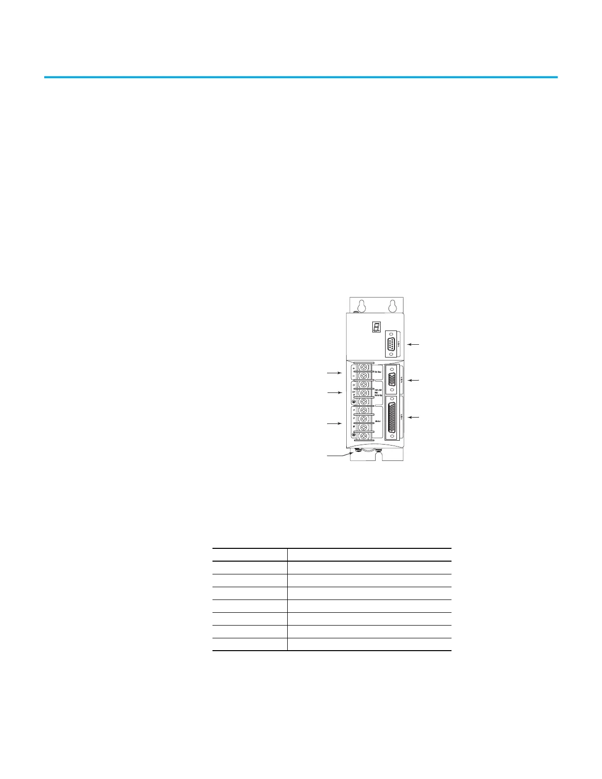
Use these illustrations to identify the connectors and indicators for Ultra3000
servo drives.
Figure 12 - Ultra3000 Servo Drive Front Panel Connections (Catalog Numbers 2098-DSD-005,
-005X, -010, -010X, -020, and -020X)
Table 44 - Ultra3000 Servo Drive Front Panel Connections Descriptions
(Cat. Nos. 2098-DSD-005, -005x, -010, -010x, -020, and -020x)
Item Description
1 DC bus connections for active shunt resistor kit
2 AC input power connections
3 Motor power connections
4 Motor power cable shield clamp
5 CN3 9-pin serial port connector
6 CN2 15-pin motor feedback connector
7 CN1 44-pin user I/O connector
1
2
3
4
5
6
7
Ultra3000 Drive, Front View
(230V [500 W, 1 kW, and 2 kW] drive is shown)

 Loading...


