52 Rockwell Automation Publication 2198-RM003B-EN-P - November 2020
Chapter 3 Connectors and Indicators
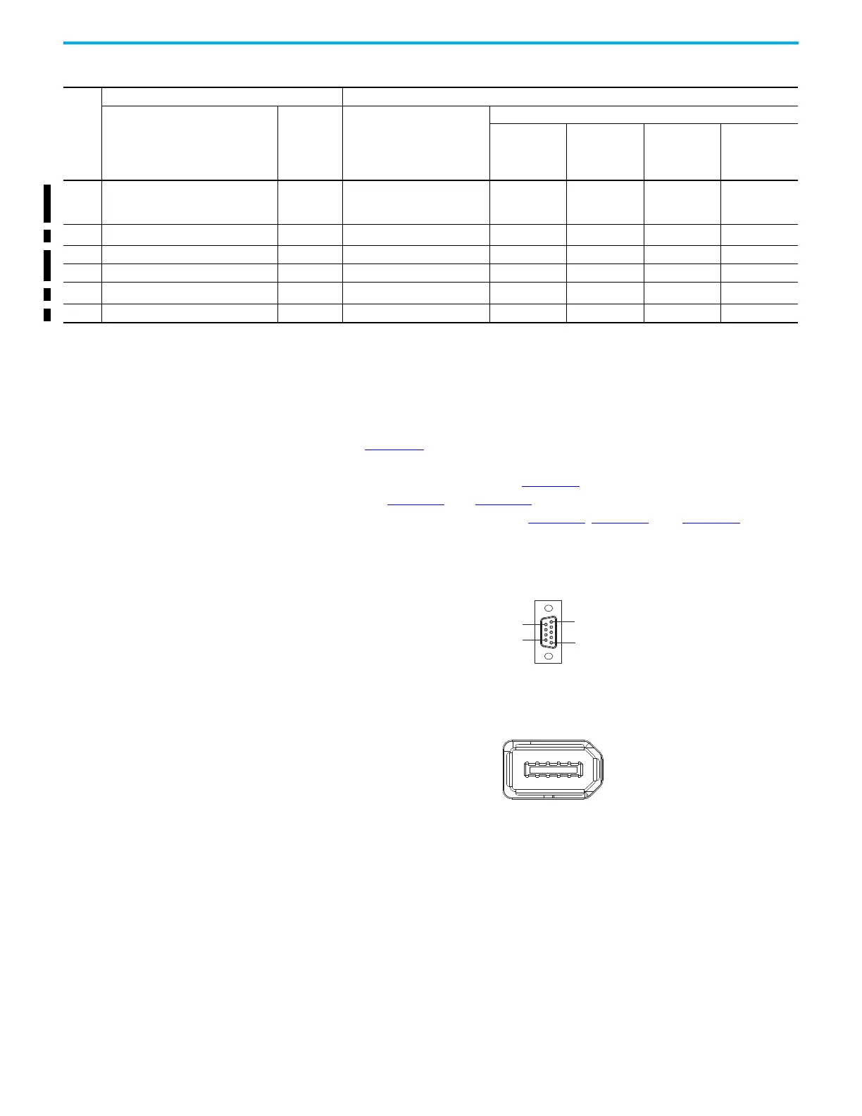
Auxiliary Feedback The Ultra3000 drives support auxiliary encoder operation. A 9-pin connector
shown in Figure 22
is used to wire an auxiliary encoder on the Ultra3000 drive.
The Kinetix 5100 drive supports auxiliary encoder operation. The 10-pin
Firewire AUX connector shown in Figure 23
, is used to wire an auxiliary
encoder. See Figure 12
and Figure 13 for locations of the auxiliary feedback
connector on Ultra3000 drives. See Figure 15
, Figure 16, and Figure 18 for the
locations of the auxiliary feedback connector on Kinetix 5100 drives
Figure 22 - 9-Pin Ultra3000 Drive Auxiliary Feedback Connector Pin Assignments
Figure 23 - 10-pin Kinetix 5100 drive Auxiliary Feedback Connector Pin Assignment
10 Channel I- / Index pulse- IM-
Data Differential Input/Output -
Index Differential Input -
MTR_DATA– MTR_T–
MTR_DATA–
(TLY-B)
MTR_SD– (TL-B)
MTR_IM–
11 Thermostat TS
Motor Thermostat
(3)
MTR_TS – – –
12 Commutation channel S1 S1 Hall Commutation S1 Input – – – MTR_S1
13 Commutation channel S2 S2 Hall Commutation S1 Input – – – MTR_S2
14 Encoder power (+5V) EPWR_5V
Encoder 5V Power Output
(4)
MTR_EPWR5V MTR_EPWR5V MTR_EPWR5V MTR_EPWR5V
15 Negative overtravel limit -LIMIT — – – – –
(1) CN2 on Ultra3000 drives. MFB on Kinetix 5100 drives.
(2) +9V encoder capability only available on standard-size Ultra3000 drive (Cat. No. 2098-DSD-030 or larger).
(3) Not applicable unless motor has integrated thermal protection.
(4) Kinetix 5100 drive encoder power supply uses either 5V or 9V DC based on encoder/motor used.
Table 48 - Motor Feedback Connectors Assignment Comparison (Continued)
Pin
(1)
Ultra3000 Drives Kinetix 5100 Drives
Description Signal Description
Signal
Hiperface
(all compatible
motors)
Nikon
(Kinetix TLP)
Tamagawa
(Kinetix TL/
TLY-B)
Digital AqB with
UVW
(all compatible
motors)
Pin 6
Pin 9
Pin 1
Pin 5

 Loading...


