106 Rockwell Automation Publication 750-TG100B-EN-P - June 2019
Chapter 6 Frame 7 Components
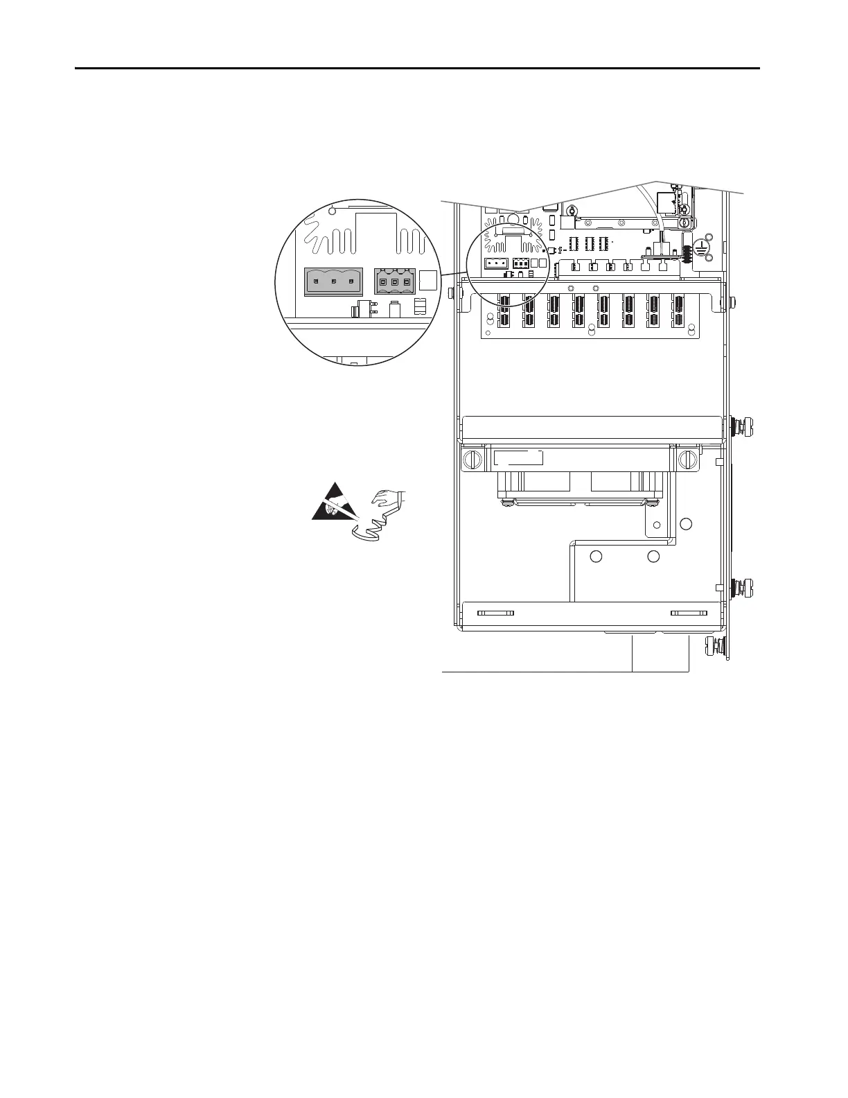
14. Disconnect connector P14 from connector J14 on the fiber-optic interface
board.
15. If installed, disconnect the customer supplied 24V supply power wire
connector P13 from connector J13 on the fiber-optic interface board.
16. Route all cables through the grommets in the bottom of the control pod.
Route Cables Through Grommets
 Loading...


