Rockwell Automation Publication 750-TG100B-EN-P - June 2019 67
Frame 5 Components Chapter 4
Power Feedback Circuit
Board and Bracket
Replacement
Replace a power feedback circuit board and bracket with kit catalog number
SK-RM-PFB-F5-F6.
Remove the Power Feedback Circuit Board and Bracket
Follow these steps to remove the power feedback circuit board and bracket.
1. Review the Product Advisories on page 14
.
2. Remove power from the system. See Remove Power from the System on
page 15
.
3. Remove the cover from the chassis. See Remove the Cover on page 56
.
4. Remove the stirring fan from the drive. See Remove the Stirring Fan
Assembly on page 61
.
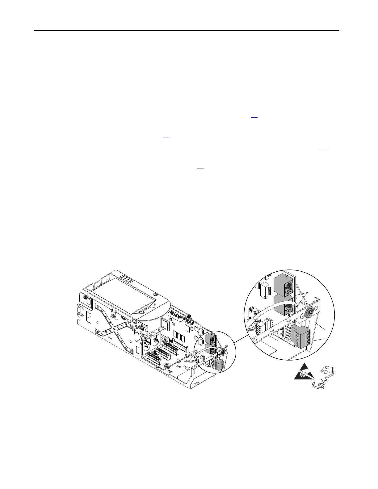
5. To prepare the control pod for removal from the drive, complete these
steps:
a. Disconnect any Ethernet cables from the ports on the bottom of the
main control board in the control pod.
b. If used, disconnect the HIM plug-in terminal block for the mini-DIN
(port 2) connector on the main control board.
c. If used, disconnect the plug-in terminal block (TB1) on the bottom of
the main control board.
d. If used, disconnect any I/O wiring terminal blocks from an installed
option module.
a
b
c
Option Modules Not
Shown for Clarity Only.
Control Pod Shown Removed
from Drive for Clarity Only.
 Loading...


