Rockwell Automation Publication 750-TG100B-EN-P - June 2019 267
Power Bay Components Chapter 9
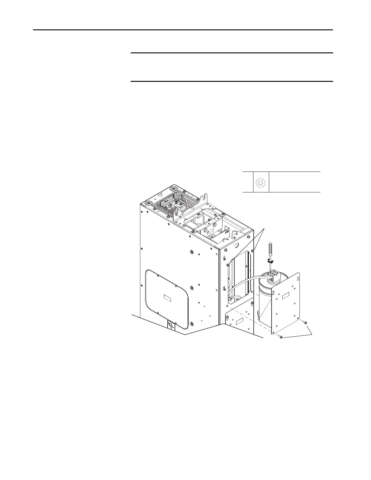
6. Complete these steps for each capacitor in the module.
a. Loosen, but do not remove, the upper two M6 x 16 mm torx screws
that secure the capacitor assembly to the chassis.
b. Remove the lower two M6 x 16 mm torx screws that secure the
capacitor assembly to the chassis.
c. Lift the capacitor assembly up and off the top screws and slide the
assembly out of the chassis.
d. Disconnect the wires from terminals at the top of the capacitor and
remove the capacitor assembly.
Install the LCL Filter Capacitor Assembly
Install the LCL filter capacitor assembly in the reverse order of removal.
IMPORTANT The interconnection wires cannot be removed from the terminal block on the
top of the capacitor until the capacitor assembly has been removed from the
chassis.
TIP The contents of the capacitor canisters is classified as not hazardous according
to regulation (EC) 1272/2008 [CLP] and classified as not dangerous according to
76/548/EEC / 1999/24/EEC.
6a,
6b
M6 x 16 mm
T30
12.5 N•m (110.6 lb•in)
6a
6b
 Loading...


