EasyManuals Logo

Rockwell Automation PowerFlex 755TL User Manual

Rockwell Automation PowerFlex 755TL
352 pages
To Next Page IconTo Next Page
To Previous Page IconTo Previous Page
Page #147 background imageLoading...
Page #147 background image
Rockwell Automation Publication 750-TG100B-EN-P - June 2019 147
Control Bay and Control Pod Components Chapter 7
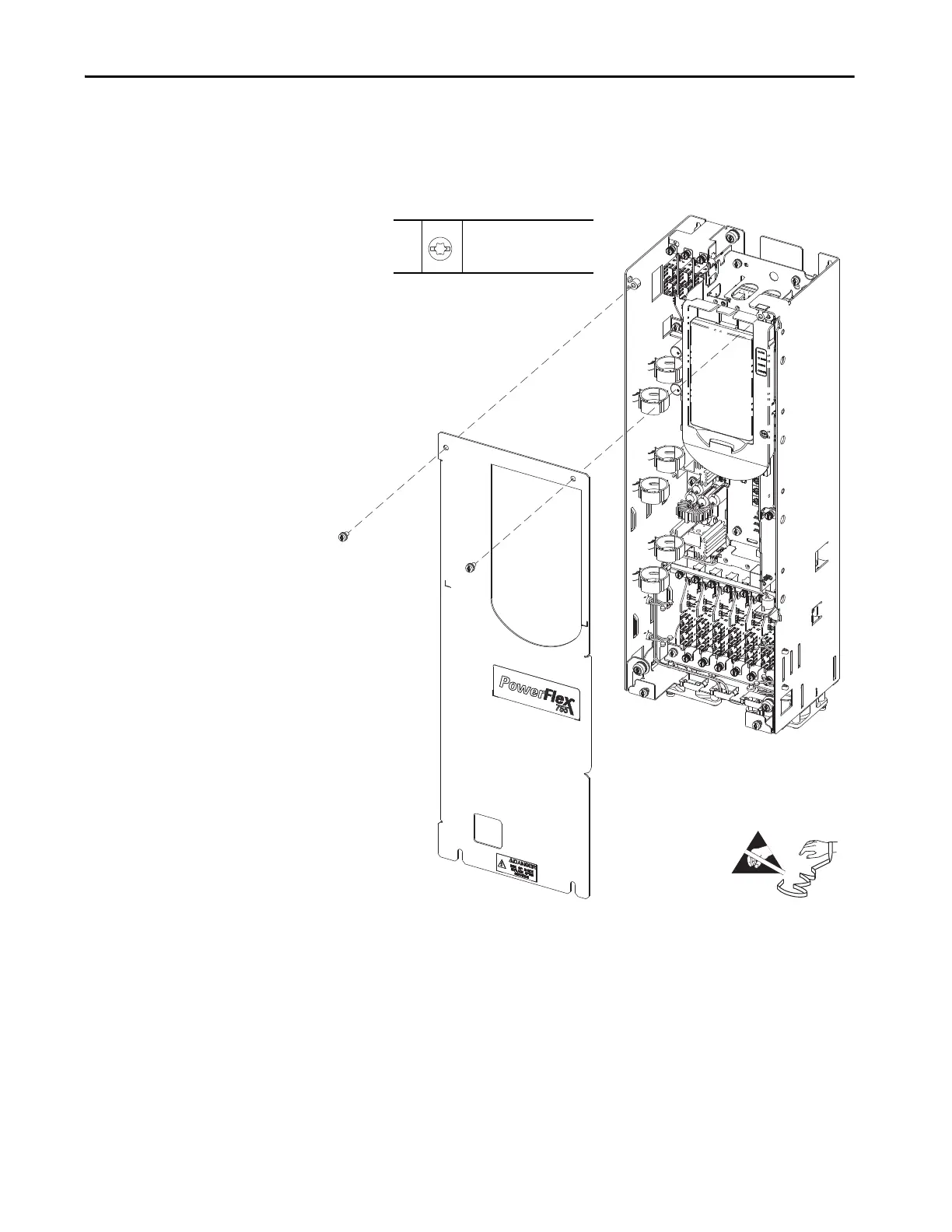
4. Loosen, but do not remove, the bottom two M4 x 8 mm slotted-torx
screws that secure the cover to the assembly.
5. Remove the top two M4 x 8 mm slotted-torx screws that secure the cover
to the assembly and remove the cover.
Install the Control Pod Cover
Install the control pod cover in the reverse order of removal.
The Control Pod is Shown Separated from the
Control/Input Bay to Clarify the Instructions Only.
4, 5
M4 x 8 mm
T20 or F - 6.4 mm (0.25 in.)
2.6 N
•m (23 lb•in)
=

Table of Contents

Questions and Answers:

Question and Answer IconNeed help?

Do you have a question about the Rockwell Automation PowerFlex 755TL and is the answer not in the manual?

Rockwell Automation PowerFlex 755TL Specifications

General IconGeneral
BrandRockwell Automation
ModelPowerFlex 755TL
CategoryDC Drives
LanguageEnglish

Related product manuals