152 Rockwell Automation Publication 750-TG100B-EN-P - June 2019
Chapter 7 Control Bay and Control Pod Components
Main Control Circuit Board
Replacement
Replace a main control circuit board with kit catalog number
SK-RM-MCB1-PF755.
Remove the Main Control Circuit Board
Follow these steps to remove the main control circuit board.
1. Review the Product Advisories on page 14
.
2. Remove power from the system. See Remove Power from the System on
page 15
.
3. Open the control bay enclosure door.
4. Remove the control pod cover. See Control Pod Cover Removal on page
146
.
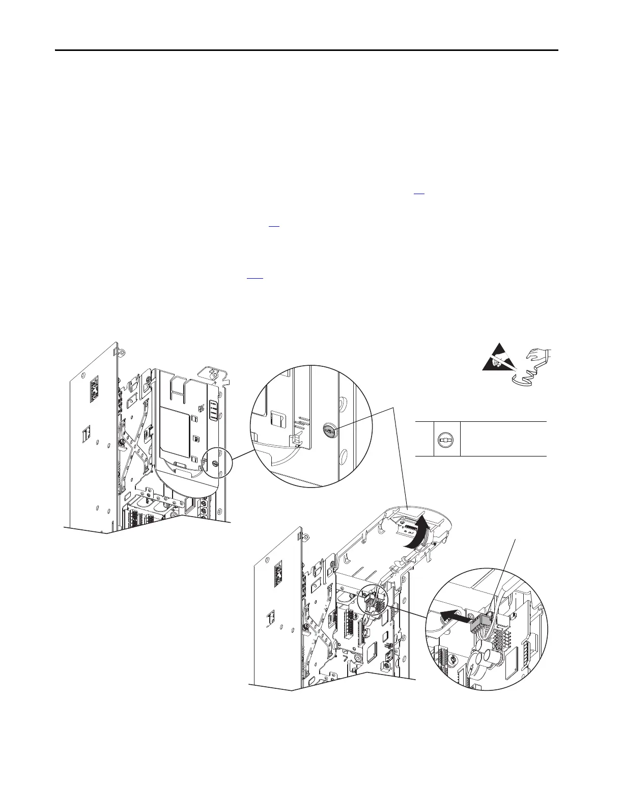
5. Loosen the screw that secures the HIM bezel to the pod chassis, and rotate
the bezel up to a 90° horizontal position.
6. Disconnect the HIM cable from the port on the main control board.
5
M3 x 6.4 mm
T15 or F - 5 mm (0.19 in.)
0.45 N•m (4 lb•in)
 Loading...


