Rockwell Automation Publication 750-TG100B-EN-P - June 2019 95
Frame 6 Components Chapter 5
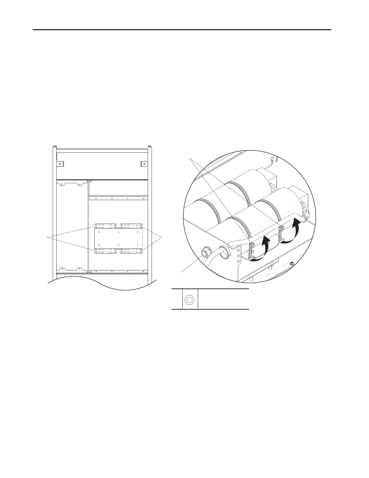
4. Insert the cable ties into the notches in the chassis mounting plate.
5. Place the capacitor into the cable ties in the drive and by inserting the
threaded screw through the mounting plate at the bottom of the
capacitors.
6. Secure the M12 hex nut to the threaded screw on the bottom of the
capacitor.
7. Secure the capacitor to the mounting plate by tightening the cable ties.
• Verify that the cable tie is aligned as it was prior to removal, with the
head of the tie to the side of the capacitor (so it does not interfere with
the cover when it is replaced).
4
4
Position the Cable Tie Heads to
the Side of the Capacitors.
6
6
M12
19 mm
9.0 N
•m (80 lb•in)
 Loading...


