250 Rockwell Automation Publication 750-TG100B-EN-P - June 2019
Chapter 9 Power Bay Components
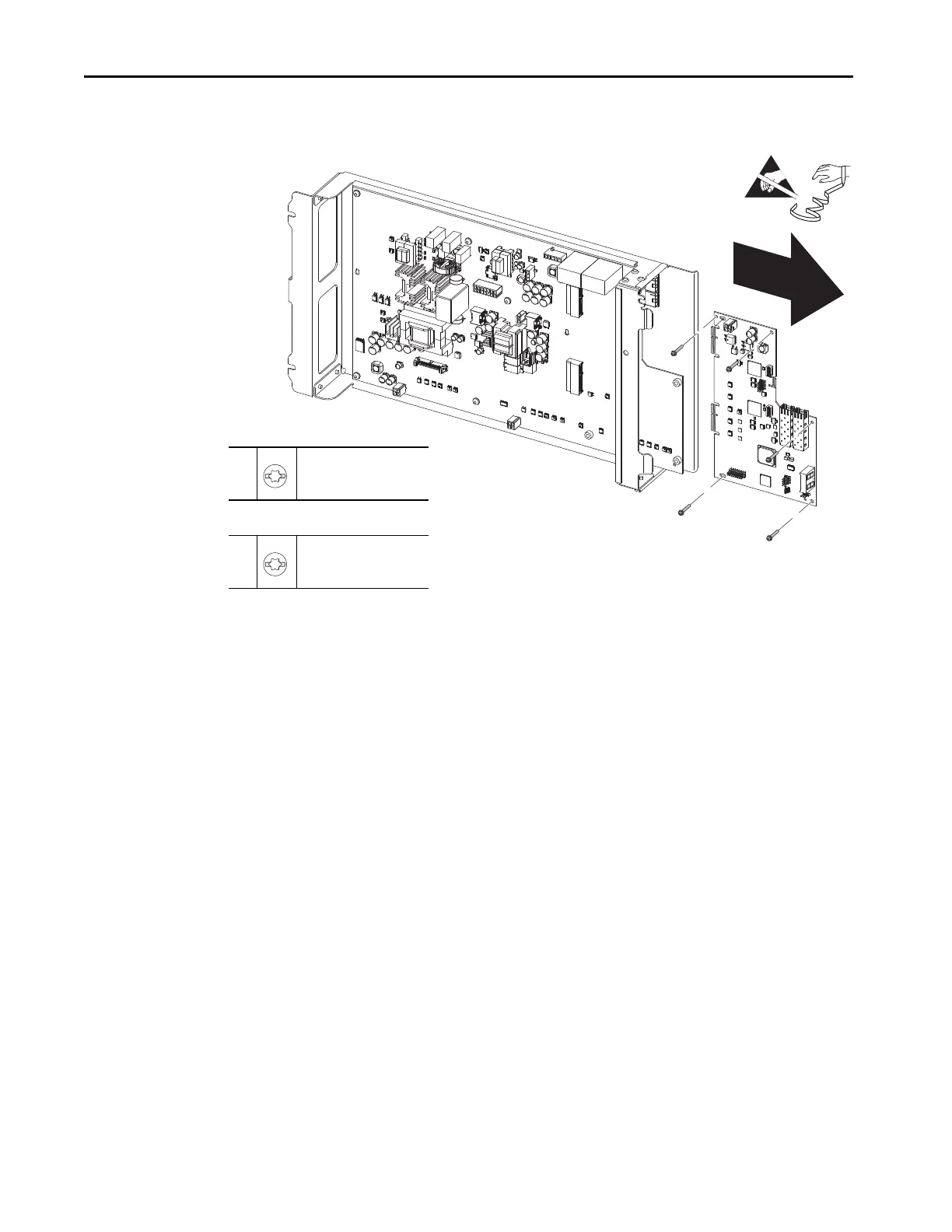
8. Slide the board to the right to disconnect the two 64-pin edge connectors
and remove the circuit board.
Install the Power Layer Interface Circuit Board
Install the power layer interface circuit board in the reverse order of removal.
Power Interface Circuit
Board Replacement
Replace the power module power interface circuit board with the appropriate kit
catalog number:
•SK-RM-PIB1-CnnnDnnn
•SK-RM-PIB1-EnnnFnnn
•SK-RM-PIB2-CnnnDnnn
•SK-RM-PIB2-EnnnFnnn
•SK-RM-PIB3-CnnnDnnn
•SK-RM-PIB3-EnnnFnnn
Two versions of the circuit board tray are released. Each version of the tray uses
different screw sizes to secure the power interface circuit board to the tray.
Circuit board trays and screw combinations for the power interface board
include:
• Part number PN-371633 contains five M4 x 10 mm slotted-torx screws
• Part number PN-417691 contains five M4 x 18 mm slotted-torx screws
7
M4 x 18 mm
T20
2.6 N•m (23.0 lb•in)
OR
7
M3 x 3 mm
T20
0.6 N•m (5.0 lb•in)
 Loading...


