244 Rockwell Automation Publication 750-TG100B-EN-P - June 2019
Chapter 9 Power Bay Components
4. If present, remove the guards from the enclosure. See Guard Removal on
page 235
.
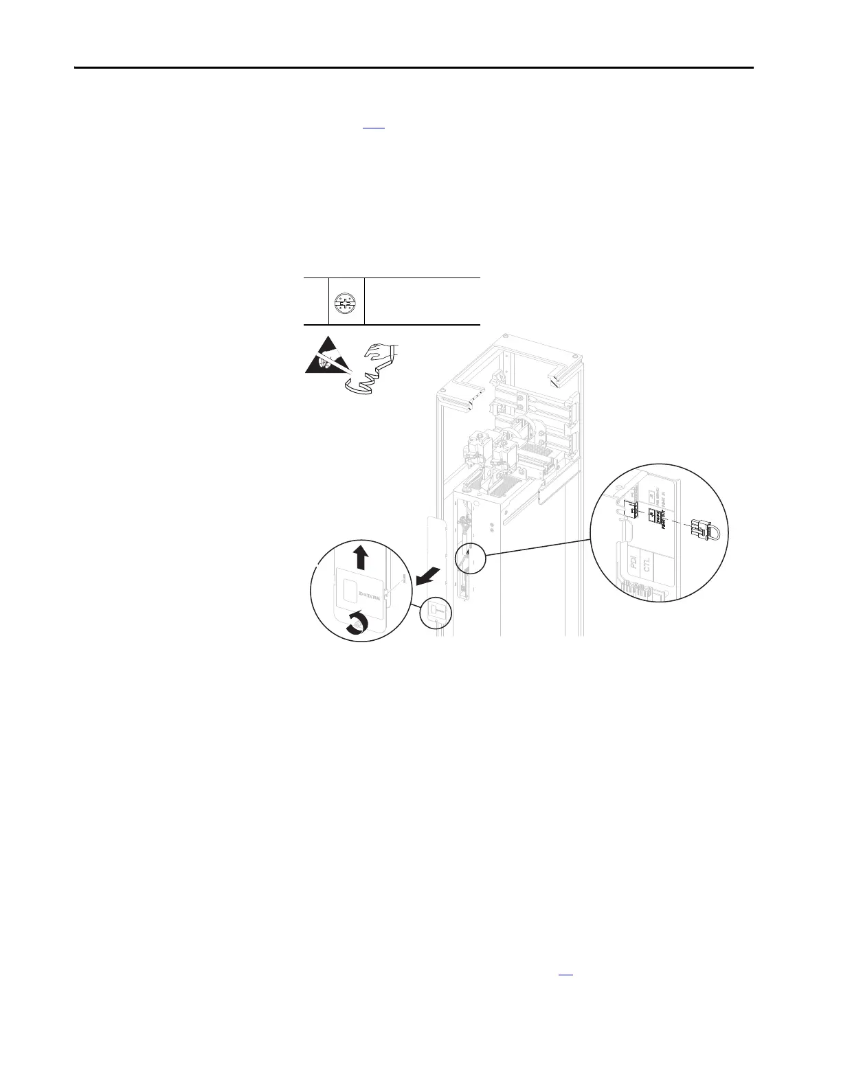
5. Loosen the torx thumb screw that secures the connections cover to the
front of the power module. 1.8 N•m (16 lb•in)
6. By using the thumb screw, lift the connections cover up and off the power
module chassis.
7. Remove the jumper from connector P5/P6 on the power layer interface
circuit board.
Install the Power Module PE-B1 Power Jumper
Install the power module PE-B1 power jumper in the reverse order of removal.
Circuit Board Tray Removal
You must remove the circuit board tray from the power module to access the
power layer interface and power interface circuit boards.
Remove the Circuit Board Tray
Follow these steps to remove the circuit board tray.
1. Review the Product Advisories on page 14
.
5
–
P2 or F - 6.4 mm (0.25 in.)
1.8 N•m (16 lb•in)
 Loading...


