270 Rockwell Automation Publication 750-TG100B-EN-P - June 2019
Chapter 9 Power Bay Components
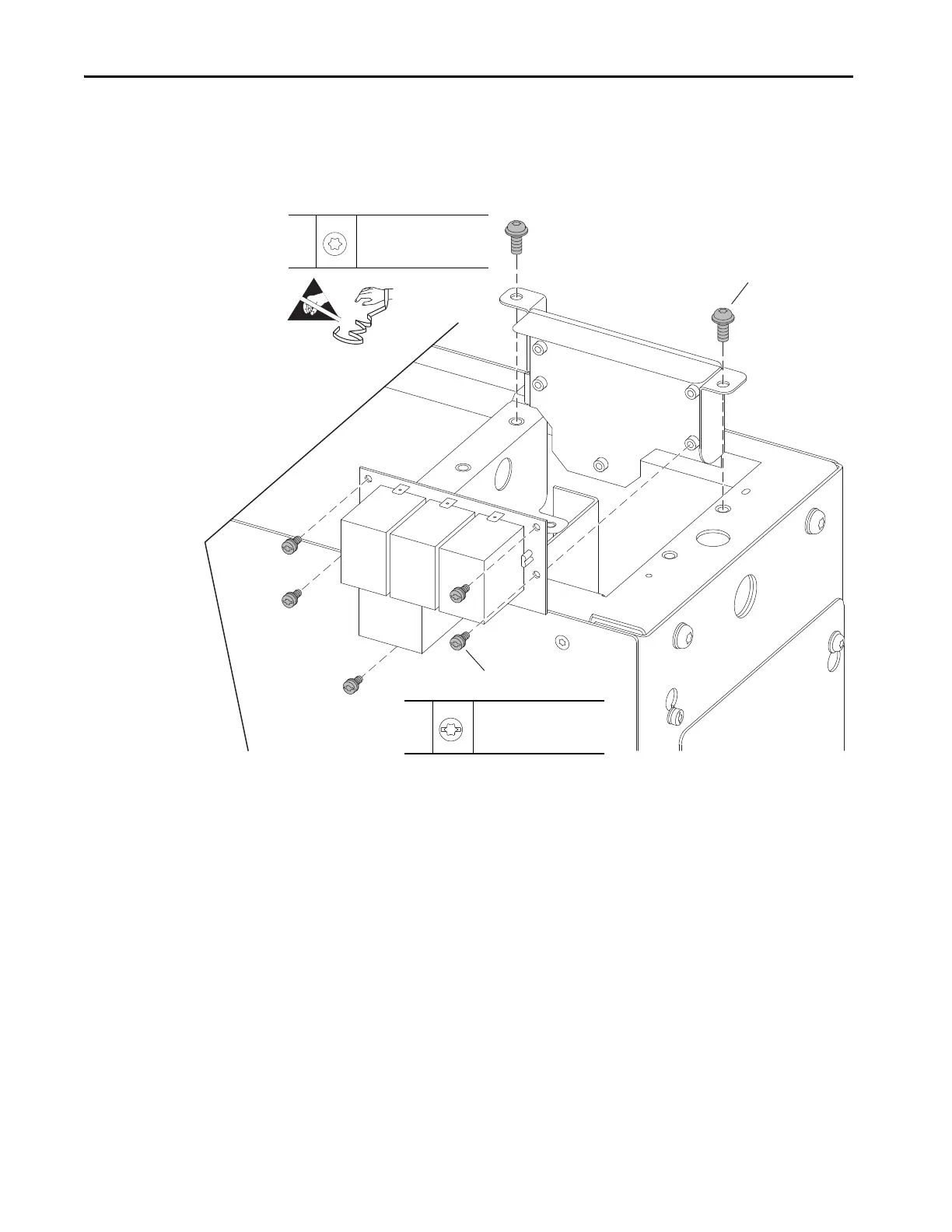
7. Remove the two M6 x 16 mm screws that secure the EMC filter circuit
board panel to the support bracket and remove the panel.
8. Remove the five M4 x 8 mm screws that secure the EMC filter circuit
board to the panel and remove the circuit board.
Install the AC Common Mode Circuit Board
Install the AC common mode filter circuit board in the reverse order of removal.
Current Sense Circuit Board
Replacement
Replace the LCL filter module current sense circuit board with the appropriate
kit catalog number:
• SK-RM-CSB1-700 (700 A)
• SK-RM-CSB1-525 (525 A)
• SK-RM-CSB1-350 (350 A)
• SK-RM-CSB1-263 (263 A)
7
M6 x 16 mm
T30
10.2 N•m (90.0 lb•in)
8
M4 x 8 mm
T20 or F - 6.4 mm (0.25 in.)
1.8 N•m (15.0 lb•in)
 Loading...


